A
PPLICATION
GUIDELINES
9
FRCC.PC.017.A1.02
E
LECTRICAL
DATA
,
CONNECTIONS
AND
WIRING
Performer
®
Heat Pump scroll compressors are available in 2 diff erent motor voltages.
Motor voltage
Performer® Heat Pump scroll compressors will
only compress gas while rotating counter-clock-
wise (when viewed from the compressor top).
Since single-phase motors will start and run in
only one direction, reverse rotation is not a ma-
jor consideration. Three-phase motors, however,
will start and run in either direction, depending
on the phase angles of the supplied power. Care
must be taken during installation to ensure that
the compressor operates in the correct direc-
tion (see “Phase sequence and reverse rotation
protection”).
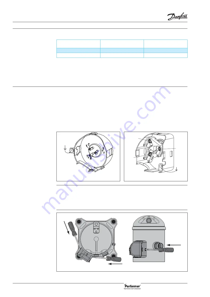
The drawings below show electrical terminal la-
belling and should be used as a reference when
wiring the compressor. For three phase applica-
tions, the terminals are labelled T1, T2, and T3.
For single-phase applications the terminals are
labelled C (common), S (start), and R (run).
Prior to energizing, verify that leads and terminal
connectors are in proper working condition.
Warning: For safety reasons, make voltage meas-
urements at the unit contactor, not at compressor
terminals. Always keep the terminal cover in place
when the compressor is energized.
The terminal cover and gasket should be installed
prior to operation of the compressor. The termi-
nal cover has two outside tabs, 180 degrees apart,
that engage the terminal fence. When installing
the cover, check that it is not pinching the lead
wires. Both the inside of the terminal cover and
the gasket have labels for the terminal pins: C
(common), R (run), and S (start).
Wiring connections
Terminal cover mounting
Terminal cover removal
Quick connect spade terminals
P terminal box type
push
push
push
Motor voltage code 4
Motor voltage code 5
Nominal voltage 50 Hz
380-400V-3-50 Hz
220-240V-1-50 Hz
Voltage range 50 Hz
340 - 440
198 - 264
Ring connect screw terminals
C terminal box type
C
T₁
S
T₂
R
T₃


