Application guidelines
17
FRCC.PC.021.A5.22
Electrical data, connections and wiring
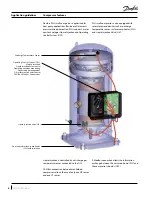
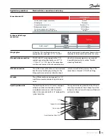
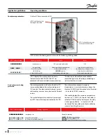
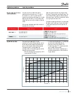
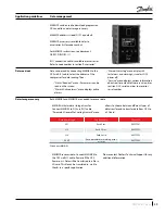
Six different knockouts are available for power
supply or accessories connections.
One double knockout for power supply:
Ø1.72" (43.7mm ) or Ø1.36" (34.5mm)
One triple knockout for power supply:
Ø1.59" (40.5mm) or Ø1.27" (32.5mm) or
Ø1" (25.4mm)
Two double knockouts for accessories:
Ø1" (25.4mm) or Ø0.78" (20mm)
Two double knockouts for accessories:
Ø0.88" (22.5mm) or Ø0.65" (16.5mm)
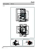
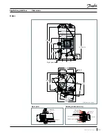
Electrical box knock-out
dimensions
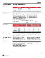
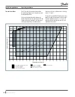
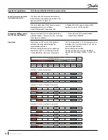
The temperature inside the terminal box must
not exceed 149°F. Above 149°F, the OCS may
not operate properly. Any compressor damaged
related to this will not be covered by Danfoss
warranty.
Consequently, if the compressor is installed in an
enclosure, precautions must be taken to avoid
that the temperature around the compressor and
in the terminal box rise too much. The installation
of ventilation on the enclosure panels may be
necessary.
In the same manner, cables must be selected in a
way to insure that terminal box temperature does
not exceed 149°F.
Electrical box temperature
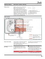
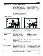
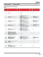
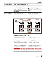
Suggested wiring diagram
Legend
Fuses ...........................................................................................................F1
Compressor contactor ........................................................................ KM
Control relay ............................................................................................ KA
Safety lock out relay ..............................................................................KS
Optional short cycle timer (3 min) ............................................. 180 s
External overload protection .............................................................F2
Pump-down pressure switch .............................................................LP
High pressure safety switch ...............................................................HP
Control device ........................................................................................ TH
Liquid line solenoid valve ............................................................... LLSV
Fused disconnect ..................................................................................Q1
Compressor motor ..................................................................................M
Thermistor chain ....................................................................................... S
Safety pressure switch ........................................................................LPS
A1
A3
A2
LP
LPS
M
S
OCS
Wiring diagram with pump-down cycle
M1 M2
A1
A3
A2
OCS
S
KS
LPS
Control circuit
Wiring diagram without pump down cycle
M1 M2
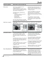
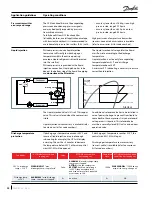
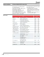
The compressor terminal box according to IEC529 is IP54 for all models when correctly sized IP54 rated
cable glands are used.
First numeral, level of protection against contact and foreign objects
5
- Dust protected
Second numeral, level of protection against water
4
- Protection against water splashing
IP rating
In specific situations, such as winter start
operation, an eventual LP control for pump-
down cycles may be temporarily bypassed to
allow the system to build pressure. But it remains
mandatory for compressor protection to apply an
LP safety switch. The LP safety switch must never
be bypassed.
Pressure settings for the LP and HP safety switch
and pump-down listed in table from section “Low
pressure”.
When ever possible (ie. PLC control), it is
recommended to limit the possibilities of
compressor auto restart to less than 3 to 5 times
during a period of 12 hours when caused by
motor protection or LP safety switch tripping.
This control must be managed as a manual reset
device.


