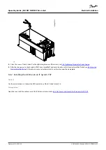
For instructions on how to install the control unit that is not attached to the power unit, see VACON
®
NXP IP00 Drives Installation
Manual.
7.2 Control Voltage (+24 V/EXT +24 V)
It is possible to use the drive with an external power source with these properties: +24 V DC ±10%, minimum 1000 mA. Use it to
externally power up the control board, and the basic and option boards. The analog outputs and inputs at OPTA1 do not work with
only +24 V supplied to the control unit.
Connect the external power source to one of the 2 bidirectional terminals (#6 or #12), see the option board manual or VACON
®
NX I/O
Boards User Manual. With this voltage, the control unit stays on and parameters can be set. The measurements of the main circuit (for
example, the DC-link voltage, and the unit temperature) are not available when the drive is not connected to mains.
NOTICE
If the AC drive is supplied with external 24 V DC power, use a diode in terminal #6 (or #12) to prevent the current to flow in
opposite direction. Put a 1 A fuse in 24 V DC line for each AC drive. The maximum current consumption of each drive is 1 A from
the external supply.
e
3
0
b
g
0
1
2
.1
0
PE/GND
-G1
Ext +24VDC
Power Supply
-F1
#6 #7
#6 #7
#6 #7
#6 #7
#6 #7
#6 #7
-F2
1A
gG/
Class CC
-Q1
3A
-Q2
3A
-Q3
3A
-Q4
3A
-Q5
3A
-Q6
3A
-F3
1A
gG/
Class CC
-F4
1A
gG/
Class CC
-F5
1A
gG/
Class CC
-F6
1A
gG/
Class CC
-F7
1A
gG/
Class CC
Illustration 45: Parallel Connection of 24 V Inputs with Many AC Drives
NOTICE
The control unit I/O ground is not isolated from the chassis ground/protective earth. In the installation, consider the potential
differences between the grounding points. We recommend using galvanic isolation in the I/O and 24 V circuitry.
Control Unit
Operating Guide | VACON® NXS/NXP Air-cooled
AQ275638903263en-000301 / DPD00910
102 | Danfoss A/S © 2020.02


