3.3.3 Additional Thermal Protection
A software temperature-protection circuit monitors filter
temperature conditions. To meet UL requirements,
additional thermal protection is provided by signals to the
line power contactors via the power card (PCA3) relay
contactor FK101. Signals are generated by a series of
thermal switches in each phase of the LM reactors and LC
reactors and through single thermal switches mounted on
the damping resistors (LCL) and IGBT module heatsinks.
Before issuing a fault and opening the contactors, the filter
will automatically try to reduce its temperature by
reducing its compensation. The line power contactors are
rated for 110–127 V and power is supplied from the soft
charge control transformer.
3.3.4 Current Transducers
Current transducers are used to monitor current in various
locations in the filter. Three current transducers on the
output-phases bus bars induce counter harmonics onto
line power. There are also three current transformers on
the line power bus bars outside of the active filter. The
information from these three transformers, via the active
filter card, is what the filter compensates for on the line
power. (For the LHD drive, these transformers are on the
line power input bus bars of the Adjustable frequency
drive for measuring the harmonics caused by the
Adjustable frequency drive.) Three other current
transducers in the LCL filter section are used for overload
protection for the AC capacitors and damping resistors.
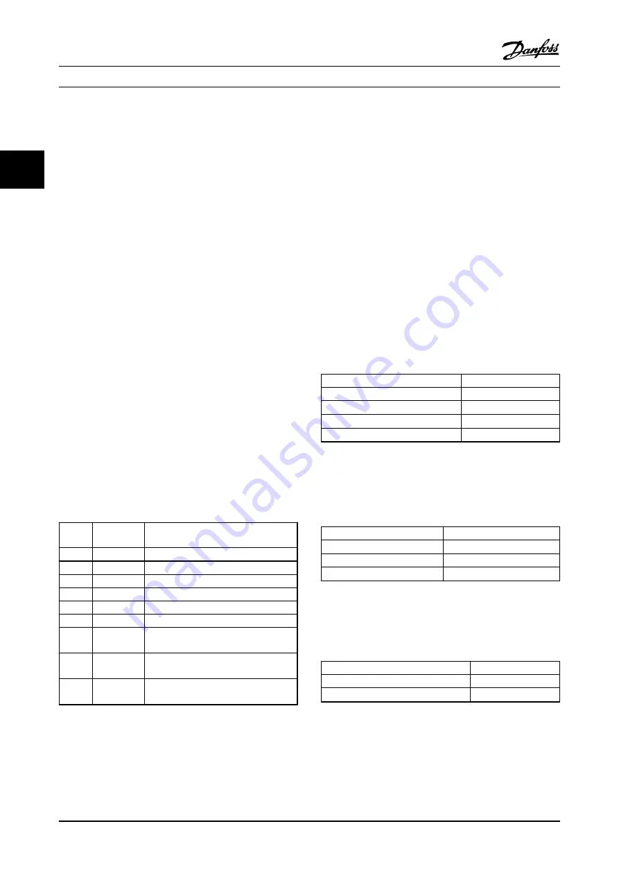
Identifi-
cation
Type
Function
CT1
Hall Effect
Output of inverter IGBT current sensor
CT2
Hall Effect
Output of inverter IGBT current sensor
CT3
Hall Effect
Output of inverter IGBT current sensor
CT4
Hall Effect
AC capacitor current sensor
CT5
Hall Effect
AC capacitor current sensor
CT6
Hall Effect
AC capacitor current sensor
CT7
Current
Transformer
External current transformer
CT8
Current
Transformer
External current transformer
CT9
Current
Transformer
External current transformer
Table 3.4 Current Transducers
3.3.5 Cooling Fans
All active filters are equipped with cooling fans to provide
airflow along the heatsink and through the doors. All fans
are powered by AC line voltage which is stepped down by
an autotransformer and regulated to 200 or 230 V AC by
circuitry provided on the power card. On/off and high/low
speed control of the fans is provided to reduce overall
acoustical noise and extend the life of the fans.
3.3.6 Fan Speed Control
The cooling fans are controlled with sensor feedback
which regulates fan operation and speed control as
described below.
1.
IGBT thermal sensor measured temperature. The
fan can be off, low speed, or high speed based
on this temperature.
IGBT Thermal Sensor
Temperature
Fan turn ON low speed
113° F [45
°
C]
Fan low speed to high speed
122° F [50
°
C]
Fan high speed to low speed
104° F [40
°
C]
Fan turn OFF from low speed
86° F [30
°
C]
Table 3.5 IGBT Thermal Sensor
2.
Power card ambient temperature sensor
measured temperature. The fan can be off or
high speed based on this temperature.
Power Card Ambient
Temperature
Fan turn ON to high speed
113° F [45
°
C]
Fan turn OFF from high speed
104° F [40
°
C]
Fan turn ON to high speed
<50° F <10
°
C
Table 3.6 Power Card Ambient Temperature Sensor
3.
Control card thermal sensor measured
temperature. The fan can be off or low speed
based on this temperature.
Control Card Ambient
Temperature
Fan turn ON to low speed
131° F [55
°
C]
Fan turn OFF from low speed
113° F [45
°
C]
Table 3.7 Control Card Thermal Sensor
4.
Current value. If the current injection is greater
than 60% of rated current, the fan will turn on
low speed.
Internal Active Filter Oper...
VLT Advanced Active Filter AAF006 D and E Frames Service Manual
3-4
MG90Z122 - VLT
®
is a registered Danfoss trademark
3
3


