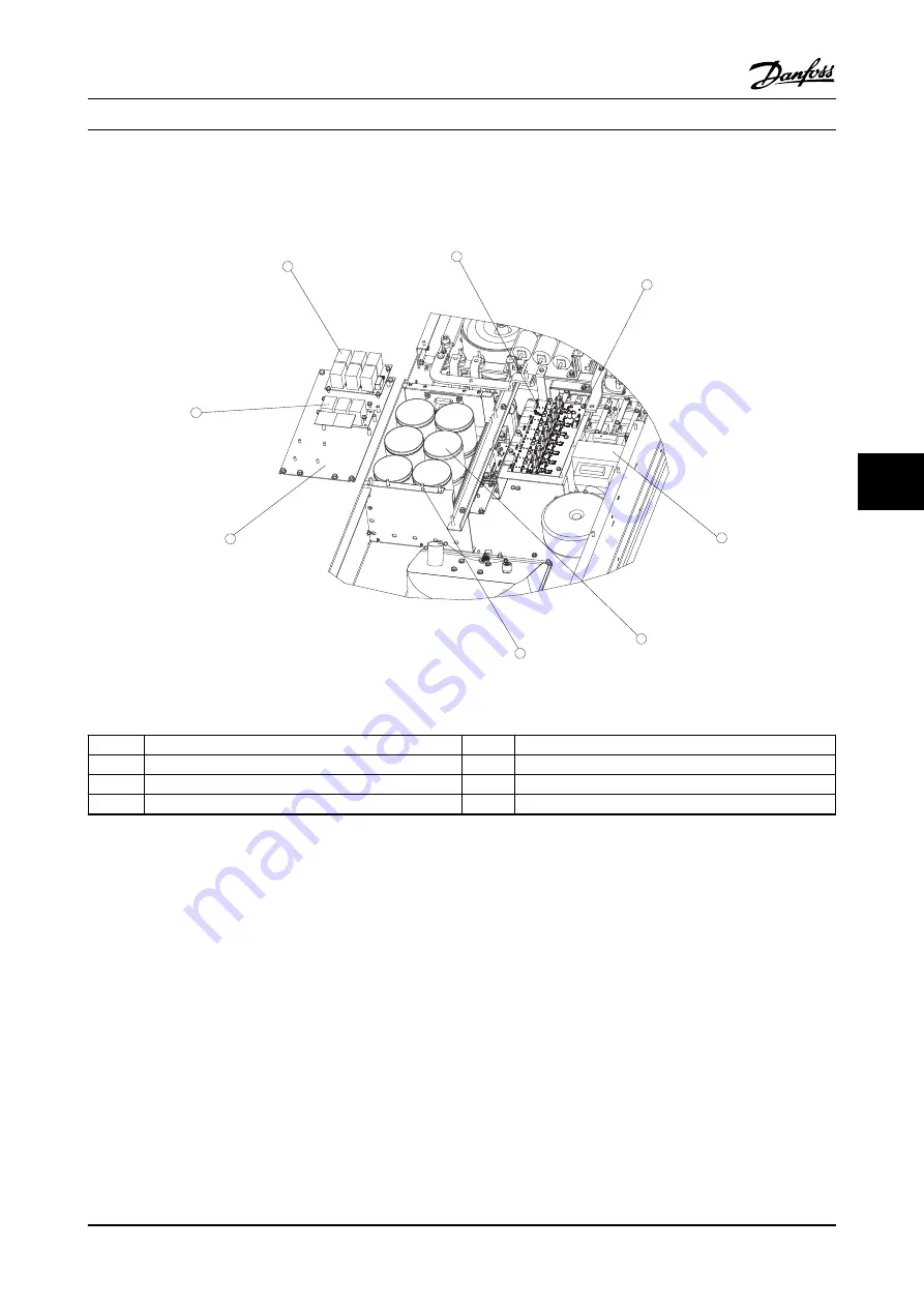
7.3.2 Gate Drive Card
1
2
3
4
5
6
7
8
H1 H2 H3 H4
X2
Fx1
x1
9T58K0070
130BX418.10
Figure 7.7 Gate Drive Card, Contactor Transformer, CM and RM RFI Cards, and Capacitor Bank Assembly
1
Common mode RFI filter
5
Capacitor bank
2
Gate drive card
6
Capacitor bank retaining screw
3
Gate drive card mounting screw
7
Capacitor bank plate
4
Contactor transformer
8
Differential mode RFI filter
Table 7.7
1.
Remove the input terminal mounting plate in
accordance with the procedure.
2.
Disconnect MK100, MK101, MK102, MK103,
MK104, and MK106 from the gate drive card.
3.
Remove the gate drive card by removing the six
screws (T-25).
Reinstall in the reverse order of this procedure. See
for torque tightening values.
7.3.3 Contactor Transformer
1.
Remove the input terminal mounting plate in
accordance with the procedure.
2.
Disconnect CM4 (not shown).
3.
Remove the contactor transformer by removing
four screws (0.39 in [10 mm]).
Reinstall in the reverse order of this procedure. See
for torque tightening values.
7.3.4 Common Mode (CM) RFI Filter Card
1.
Disconnect the cables from MK1, MK5, MK6, and
MK7.
2.
Remove the common mode RFI filter card by
removing the four screws (T-25) from the
standoffs.
Reinstall in the reverse order of this procedure. See
for torque tightening values.
D-Frame Sizes Disassembly a...
VLT Advanced Active Filter AAF006 D and E Frames Service Manual
MG90Z122 - VLT
®
is a registered Danfoss trademark
7-11
7
7


