3.3 Parameter Group 1-** Load and Motor
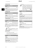
3.3.1 Configuration
Selection of configuration and torque characteristics has an effect on
which parameters can be seen in the display. If
Open loop
[0] is selected,
all parameters relating to PID regulation will be filtered out. This means
that the user only sees the parameters that are relevant for a given ap-
plication.
100
Configuration
Value:
Speed control, open loop
(SPEED OPEN LOOP)
[0]
Speed control, closed loop
(SPEED CLOSED LOOP)
[1]
Process control, closed loop
(PROCESS CLOSED LOOP)
[3]
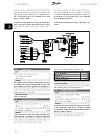
Function:
This parameter is used to select the configuration to which the frequency
converter is to be adapted. This makes adaptation to a given application
simple, since the parameters not used in a given configuration are hidden
(not active).
Description of choice:
If
Speed control, open loop
[0] is selected, normal speed control is ob-
tained (without feedback signal) with automatic load and slip compen-
sation to ensure a constant speed at varying loads. Compensations are
active, but may be disabled in parameter 134
Load compensation
and
parameter 136
Slip compensation
as required.
If
Speed control, closed loop
[1] is selected, better speed accuracy is
obtained. A feedback signal must be added, and the PID regulator must
be set in parameter group 400
Special functions
.
If
Process control, closed loop
[3] is selected, the internal process regu-
lator is activated to enable precise control of a process in relation to a
given process signal. The process signal can be set to the relevant process
unit or as a percentage. A feedback signal must be added from the proc-
ess and the process regulator must be set in parameter group 400
Special
functions
. Process closed loop is not active if a DeviceNet card is mounted
and Instance 20/70 or 21/71 is chosen in parameter 904
Instance
types
.
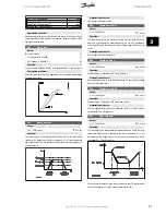
101
Torque characteristic
Value:
Constant torque
(Constant torque)
[1]
Variable torque low
(torque: low)
[2]
Variable torque medium
(torque: med)
[3]
Variable torque high
(torque: high)
[4]
Variable torque low with CT start
(VT LOW CT START)
[5]
Variable torque medium with CT start
(VT MED CT START)
[6]
Variable torque high with CT start
(VT HIGH CT START)
[7]
Special motor mode
(Special motor mode)
[8]
CT = Constant torque
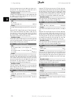
Function:
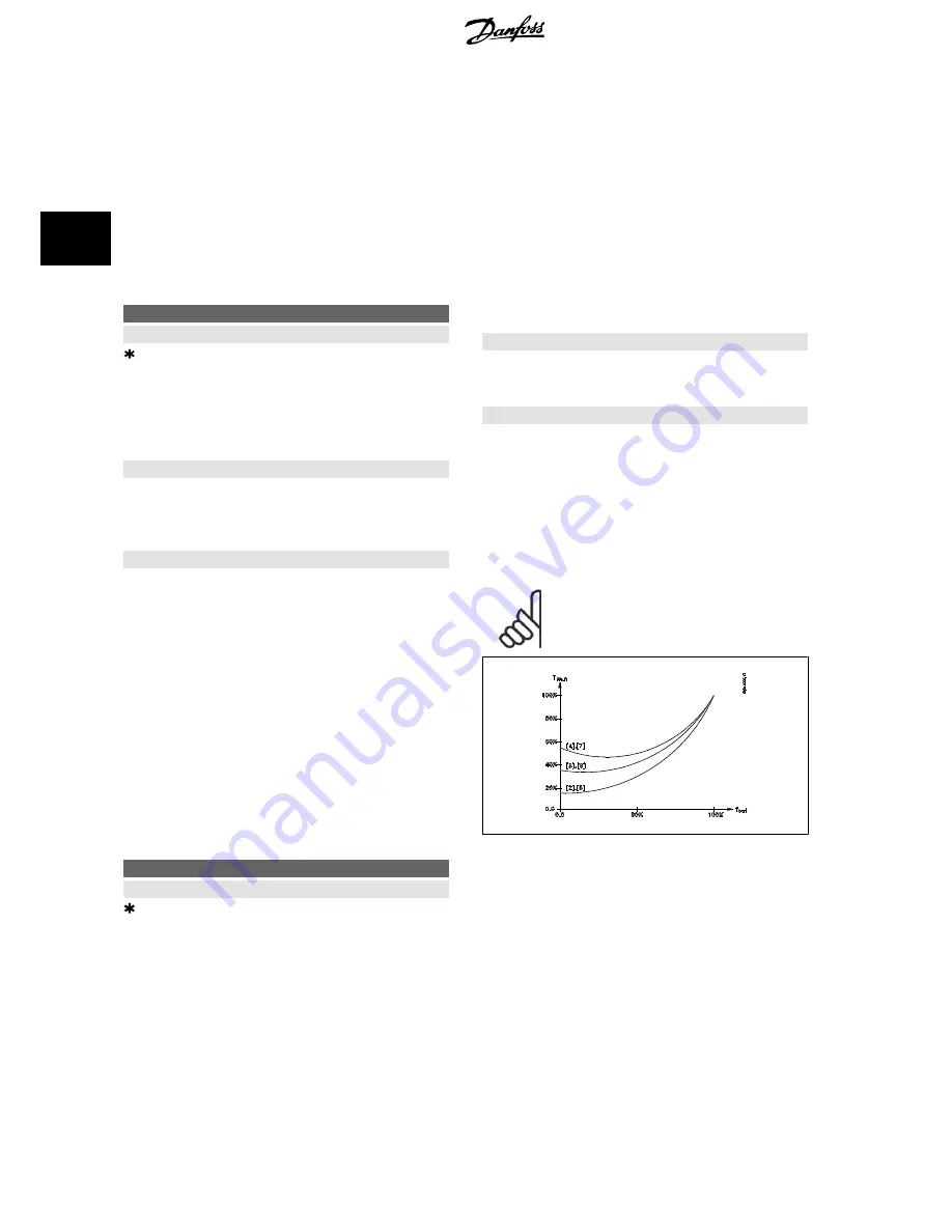
This parameter enables a choice of principle for adaptation of the U/f ratio
of the frequency converter to the torque characteristic of the load. See
par. 135
U/f ratio.
Description of choice:
If
Constant torque
[1] is selected, a load-dependent U/f characteristic is
obtained, in which output voltage and output frequency are increased at
increasing loads in order to maintain constant magnetization of the mo-
tor.
Select
Variable torque low
[2],
Variable torque medium
[3] or
Variable
torque high
[4], if the load is square (centrifugal pumps, fans).
Variable torque - low with CT start
[5],
- medium with CT start
[6] or
high with CT start
[7], are selected if you need a greater breakaway tor-
que than can be achieved with the three first characteristics.
NB!
Load and slip compensation are not active if variable
torque or special motor mode have been selected.
Select
Special motor mode
[8], if a special U/f setting is needed that is to
be adapted to the present motor. The break points are set in parameters
423-428
Voltage/frequency
.
3 Programming
VLT® Decentral FCD
42
MG.04.B8.02 - VLT is a registered Danfoss trademark
3
Summary of Contents for VLT Decentral FCD 300
Page 112: ......


