background image

10 Specifications

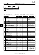
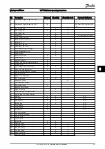
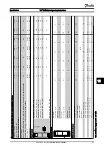
10.1  Power-dependent Specifications

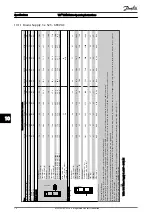
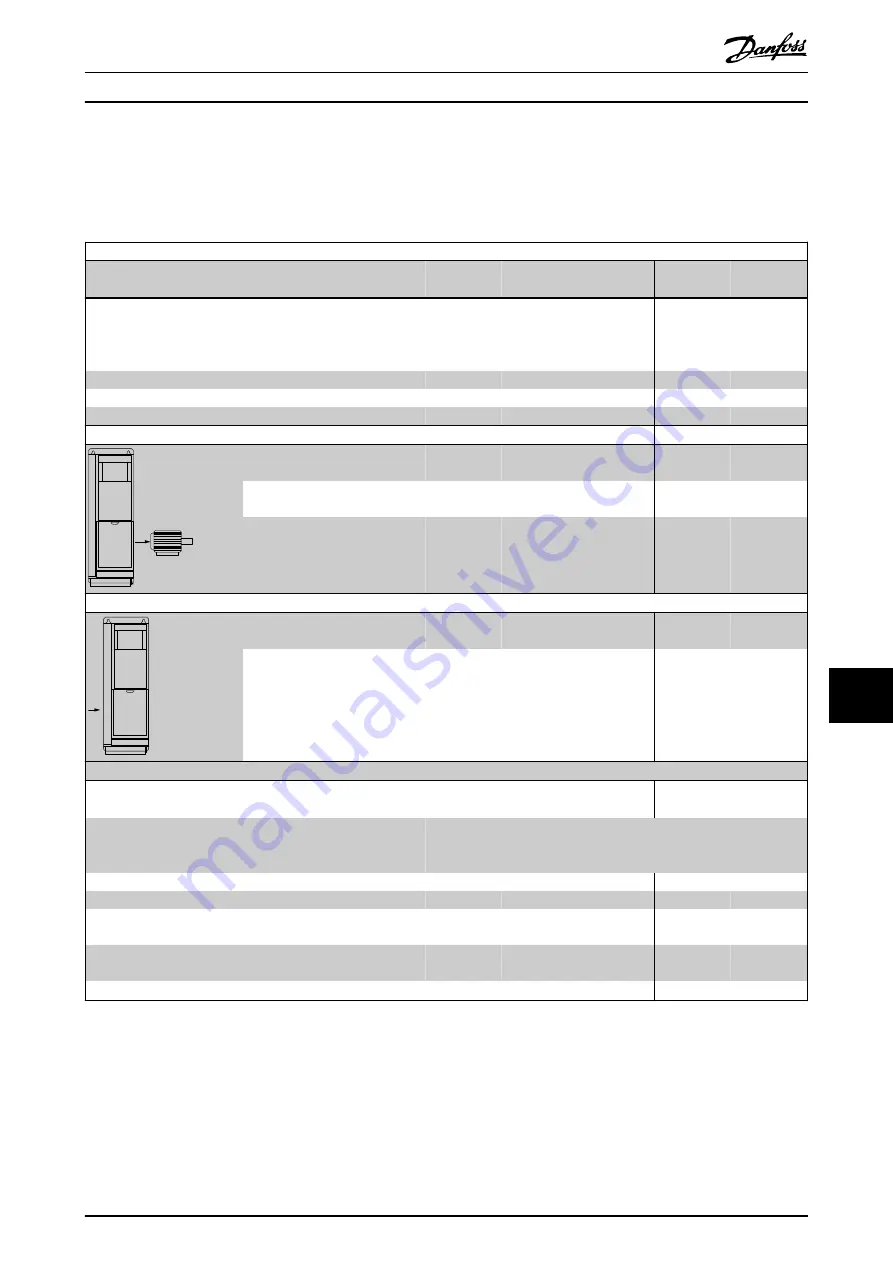
Mains supply 200 - 240 V AC - Normal overload 110% for 1 minute
Frequency converter
Typical Shaft Output [kW]

P1K1

1.1

P1K5

1.5

P2K2

2.2

P3K0

3

P3K7

3.7

IP20/Chassis
(A2+A3 may be converted to IP21 using a conversion kit. (Please
also see 

Mechanical mounting

 and 

IP21/Type 1 Enclosure kit

 in

the Design Guide.))

A2

A2

A2

A3

A3

IP55/Type 12


A4/A5

A4/A5

A4/A5

A5

A5

IP66/NEMA 4X


A4/A5

A4/A5

A4/A5

A5

A5

Typical Shaft Output [HP] at 208 V

1.5

2.0

2.9

4.0

4.9

Output current


130BA058.10

Continuous
(3 x 200-240 V) [A]

6.6

7.5

10.6

12.5

16.7

Intermittent
(3 x 200-240 V) [A]

7.3

8.3

11.7

13.8

18.4

Continuous
kVA (208 V AC) [kVA]

2.38

2.70

3.82

4.50

6.00

Max. input current

130BA057.10

Continuous
(3 x 200-240 V) [A]

5.9

6.8

9.5

11.3

15.0

Intermittent
(3 x 200-240 V) [A]

6.5

7.5

10.5

12.4

16.5

Additional specifications
 

Estimated power loss
at rated max. load [W] 

4)

63

82

116

155

185


Max. cable size (mains, motor,
brake)
[mm

2

 /AWG] 

2)

4/10


Weight enclosure IP20 [kg]

4.9

4.9

4.9

6.6

6.6


Weight enclosure IP21 [kg]

5.5

5.5

5.5

7.5

7.5


Weight enclosure IP55 [kg]
(A4/A5)

9.7/13.5

9.7/13.5

9.7/13.5

13.5

13.5


Weight enclosure IP66 [kg]
(A4/A5)

9.7/13.5

9.7/13.5

9.7/13.5

13.5

13.5


Efficiency 

3)

0.96

0.96

0.96

0.96

0.96

Table 10.1 Mains Supply 200 - 240 V AC

Specifications

VLT

®

 HVAC Drive Operating Instructions

MG11AH02 - VLT

®

 is a registered Danfoss trademark

65

10

10

Summary of Contents for VLT HVAC

Page 1: ...MAKING MODERN LIVING POSSIBLE Operating Instructions VLT HVAC Drive...

Page 2: ...in charged even when the frequency converter is not powered To avoid electrical hazards disconnect AC mains any permanent magnet type motors and any remote DC link power supplies including battery bac...

Page 3: ...Safety VLT HVAC Drive Operating Instructions MG11AH02 VLT is a registered Danfoss trademark...

Page 4: ...4 2 4 2 2 Grounding Using Shielded Cable 14 2 4 3 Motor Connection 15 2 4 4 AC Mains Connection 16 2 4 5 Control Wiring 16 2 4 5 1 Access 16 2 4 5 2 Control Terminal Types 17 2 4 5 3 Wiring to Control...

Page 5: ...ialisation 33 5 About Frequency Converter Programming 34 5 1 Introduction 34 5 2 Programming Example 34 5 3 Control Terminal Programming Examples 35 5 4 International North American Default Parameter...

Page 6: ...ifications 65 10 2 General Technical Data 71 10 3 Fuse Tables 76 10 3 1 Branch Circuit Protection Fuses 76 10 3 2 UL and cUL Branch Circuit Protection Fuses 77 10 3 3 Substitute Fuses for 240 V 78 10...

Page 7: ...lug 13 Brake 81 82 and load sharing 88 89 terminals 5 Analog switches A53 A54 14 Mains input terminals 91 L1 92 L2 93 L3 6 Cable strain relief PE ground 15 USB connector 7 Decoupling plate 16 Serial b...

Page 8: ...ector 13 Mounting slot 4 Digital I O and 24 V power supply 14 Grounding clamp PE 5 Analog I O connector 15 Cable strain relief PE ground 6 Cable strain relief PE ground 16 Brake terminal 81 82 7 USB c...

Page 9: ...ctions supplied with those options for specific requirements Contact the local Danfoss supplier or go to http www danfoss com Products Literature Technical Documentation htm for downloads or additiona...

Page 10: ...r bank Stores the DC power Provides ride through protection for short power losses 6 Inverter Converts the DC into a controlled PWM AC waveform for a controlled variable output to the motor 7 Output t...

Page 11: ...1 15 18 5 18 5 30 37 45 22 30 37 45 380 480 1 1 4 0 5 5 7 5 0 37 4 0 1 1 7 5 11 18 5 22 30 11 18 5 22 37 37 55 75 90 45 55 75 90 525 600 n a 1 1 7 5 n a 1 1 7 5 11 18 5 22 30 11 18 5 22 37 37 55 75 90...

Page 12: ...fy the proper equipment Ensure each of the following are rated for same voltage Mains power Frequency converter Motor Ensure that frequency converter output current rating is equal to or greater than...

Page 13: ...to the optional back plate to provide cooling airflow see Illustration 2 2 and Illustration 2 3 Improper mounting can result in over heating and reduced performance Use the slotted mounting holes on t...

Page 14: ...M D IN 15mA 200mA U 96 V 97 W 98 PE 99 COM A OUT 39 A OUT 42 0 4 20 mA 03 0 10Vdc 10Vdc 0 10Vdc 0 4 20 mA 240Vac 2A 24Vdc 02 01 05 04 06 240Vac 2A 24V NPN 0V PNP 0V PNP 24V NPN 19 D IN 24V NPN 0V PNP...

Page 15: ...and mains 2 Frequency converter 7 Motor 3 phase and PE 3 Output contactor Generally not recommended 8 Mains 3 phase and reinforced PE 4 Earth grounding rail PE 9 Control wiring 5 Cable insulation str...

Page 16: ...level of increase to activate timing for the trip controller output stop function The higher the current draw the quicker the trip response The overload provides Class 20 motor protection See 8 Warni...

Page 17: ...mA Frequency converter technology implies high frequency switching at high power This will generate a leakage current in the earth connection A fault current in the frequency converter at the output p...

Page 18: ...the frequency converter and the motor Connect the 3 phase motor wiring to terminals 96 U 97 V and 98 W Ground the cable in accordance with grounding instructions provided Torque terminals in accordanc...

Page 19: ...well as with ground reference power lines When supplied from an isolated mains source IT mains or floating delta or TT TN S mains with a grounded leg grounded delta set 14 50 RFI Filter to OFF When of...

Page 20: ...igital terminals programmable as either input or output a 24 V DC terminal supply voltage and a common for optional customer supplied 24 V DC voltage Connector 2 terminals 68 and 69 are for an RS 485...

Page 21: ...the screen when experiencing EMC problems Terminal Description Digital Inputs Outputs Terminal Parameter Default Setting Description 68 8 3 RS 485 Interface A control card switch is provided for termi...

Page 22: ...PE PE 69 69 68 68 1 2 Illustration 2 21 2 4 5 5 Control Terminal Functions Frequency converter functions are commanded by receiving control input signals Each terminal must be programmed for the func...

Page 23: ...situations In the normal operating mode when safe stop is not required use the frequency converter s regular stop function instead When automatic restart is used the requirements according to ISO 121...

Page 24: ...ent magnet motor frequency converters in case of a multiple IGBT power semiconductor failure In spite of the activation of the Safe torque off function the frequency converter system can produce an al...

Page 25: ...or Coast 9 5 V DC 4 Frequency converter 10 Safe channel 5 Mains 11 Short circuit protected cable if not inside installation cabinet 6 Control board Table 2 5 Safe Stop Commissioning Test After install...

Page 26: ...r Frewheeling diode Brake 380Vac Output Contactor Input Power Circuit Illustration 2 25 Connecting the Mechanical Brake to the Frequency Converter 2 4 6 Serial Communication RS 485 is a two wire bus i...

Page 27: ...nverter disconnect switches for input power isolation 2 Verify that there is no voltage on input terminals L1 91 L2 92 and L3 93 phase to phase and phase to ground 3 Verify that there is no voltage on...

Page 28: ...ing EMC considerations Check for proper installation regarding electromagnetic compatibility Environmental considerations See equipment label for the maximum ambient operating temperature limits Humid...

Page 29: ...ency converters require basic operational programming before running for best performance Basic operational programming requires entering motor nameplate data for the motor being operated and the mini...

Page 30: ...const 1 24 Motor Current 1 25 Motor Nominal Speed 1 26 Motor Cont Rated Torque 1 30 Stator Resistance Rs 1 37 d axis Inductance Ld 1 39 Motor Poles 1 40 Back EMF at 1000 RPM 1 66 Min Current at Low S...

Page 31: ...s complete 3 6 Check Motor Rotation before running the frequency converter check the motor rotation The motor will run briefly at 5Hz or the minimum frequency set in 4 12 Motor Speed Low Limit Hz 1 Pr...

Page 32: ...help with this task Other aids to application set up are listed in 1 2 Additional Resources The following procedure is recommended after application set up by the user is completed CAUTION MOTOR START...

Page 33: ...on use of the NLCP NOTE The display contrast can be adjusted by pressing Status and the up down key 4 1 1 LCP Layout The LCP is divided into four functional groups see Illustration 4 1 Auto on Reset H...

Page 34: ...Key Function Status Press to show operational information In Auto mode press and hold to toggle between status read out displays Press repeatedly to scroll through each status display Press and hold S...

Page 35: ...nd at the bottom of the LCP 130BP046 10 Hand on Off Auto on Reset Illustration 4 6 Key Function Hand On Press to start the frequency converter in local control Use the navigation keys to control frequ...

Page 36: ...on can be through 14 22 Operation Mode or manually Initialisation using 14 22 Operation Mode does not change frequency converter data such as operating hours serial communication selections personal m...

Page 37: ...rams the frequency converter to receive a 0 10 V DC analog control signal on input terminal 53 The frequency converter will respond by providing 6 60 Hz output to the motor propor tional to the input...

Page 38: ...t in the last illustration of the display is at the bottom indicating the procedure is complete Illustration 5 8 shows the wiring connections used to enable this set up 53 55 6 1 A53 U I 130BB482 10 0...

Page 39: ...Hz 4 19 Max Output Frequency 132 Hz 120 Hz 4 53 Warning Speed High 1500 RPM 1800 RPM 5 12 Terminal 27 Digital Input Coast inverse External interlock 5 40 Function Relay No operation No alarm 6 15 Term...

Page 40: ...applications often requires setting functions in several related parameters These parameter settings provide the frequency converter with system details it needs to operate properly System details ma...

Page 41: ...ettings 5 15 Terminal 33 Digital Input 20 21 Setpoint 1 6 22 Terminal 54 Low Current 20 01 Feedback 1 Conversion 0 70 Date and Time Q3 21 Analog Reference 20 81 PID Normal Inverse Control 6 24 Termina...

Page 42: ...5 Short Cycle Protection 6 23 Terminal 54 High Current 20 73 Minimum Feedback Level 2 10 Brake Function 22 46 Maximum Boost Time 22 76 Interval between Starts 6 24 Terminal 54 Low Ref Feedb Value 20 7...

Page 43: ...mps 3 80 Jog Ramp Time 3 81 Quick Stop Ramp Time 3 82 Starting Ramp Up Time 3 9 Digital Pot Meter 3 90 Step Size 3 91 Ramp Time 3 92 Power Restore 3 93 Maximum Limit 3 94 Minimum Limit 3 95 Ramp Delay...

Page 44: ...e 12 21 Process Data Config Write 12 22 Process Data Config Read 12 27 Primary Master 12 28 Store Data Values 12 29 Store Always 12 3 EtherNet IP 12 30 Warning Parameter 12 31 Net Reference 12 32 Net...

Page 45: ...PID Anti Windup 20 93 PID Proportional Gain 20 94 PID Integral Time 20 95 PID Differentiation Time 20 96 PID Diff Gain Limit 21 Ext Closed Loop 21 0 Ext CL Autotuning 21 00 Closed Loop Type 21 01 PID...

Page 46: ...Ref Feedb Value 26 26 Term X42 3 Filter Time Constant 26 27 Term X42 3 Live Zero 26 3 Analog Input X42 5 26 30 Terminal X42 5 Low Voltage 26 31 Terminal X42 5 High Voltage 26 34 Term X42 5 Low Ref Fe...

Page 47: ...e off line and simply downloaded to thefrequency converter Or the entire frequency converter profile can be loaded onto the PC for back up storage or analysis The USB connector or RS 485 terminal are...

Page 48: ...ital Input 2 Coast inverse Default Value Notes comments Parameter group 1 2 must be set according to motor Table 6 1 AMA with T27 Connected Parameters FC 24 V 24 V D IN D IN D IN COM D IN D IN D IN D...

Page 49: ...Terminal 37 Safe Stop 1 Safe Stop Alarm Default Value Notes comments If 5 12 Terminal 27 Digital Input is set to 0 No operation a jumper wire to terminal 27 is not needed Table 6 5 Start Stop Command...

Page 50: ...ue Notes comments Table 6 8 External Alarm Reset Parameters FC 24 V 24 V D IN D IN D IN COM D IN D IN D IN D IN 10 V A IN A IN COM A OUT COM 12 13 18 19 20 27 29 32 33 37 50 53 54 55 42 39 A53 U I 5k...

Page 51: ...1 RS 485 Network Connection CAUTION Thermistors must use reinforced or double insulation to meet PELV insulation requirements Parameters FC 24 V 24 V D IN D IN D IN COM D IN D IN D IN D IN 10 V A IN A...

Page 52: ...ed External equipment may then indicate that service may be required If the feedback error goes below the limit again within 5 sec then the drive continues and the warning disappears But Relay 1 will...

Page 53: ...inals and or the serial communi cation Hand On The frequency converter can be controlled by the navigation keys on the LCP Stop commands reset reversing DC brake and other signals applied to the contr...

Page 54: ...Down Operation Status Jog request A jog command has been given but the motor will be stopped until a run permissive signal is received via a digital input Jogging The motor is running as programmed i...

Page 55: ...n 1 71 Start Delay a delay starting time was set A start command is activated and the motor will start after the start delay time expires Start fwd rev Start forward and start reverse were selected as...

Page 56: ...fault condition is remedied the frequency converter can be reset It will then be ready to start operation again A trip can be reset in any of 4 ways Press Reset on the LCP Digital reset input command...

Page 57: ...Short Circuit X X 17 Control word timeout X X 8 04 Control Timeout Function 18 Start Failed 23 Internal Fan Fault X 24 External Fan Fault X 14 53 Fan Monitor 25 Brake resistor short circuited X 26 Bra...

Page 58: ...Over temperature X X X 66 Heat sink Temperature Low X 67 Option Configuration has Changed X 69 Pwr Card Temp X X 70 Illegal FC configuration X 71 PTC 1 Safe Stop X X1 72 Dangerous Failure X1 73 Safe S...

Page 59: ...The intermediate circuit voltage DC is higher than the high voltage warning limit The limit is dependent on the frequency converter voltage rating The unit is still active WARNING 6 DC link voltage l...

Page 60: ...by an alarm Troubleshooting If the motor torque limit is exceeded during ramp up extend the ramp up time If the generator torque limit is exceeded during ramp down extend the ramp down time If torque...

Page 61: ...esistance value set in 2 16 AC brake Max Current The warning is active when the dissipated braking is higher than 90 of the brake resistance power If Trip 2 is selected in 2 13 Brake Power Monitoring...

Page 62: ...IGBT thermal sensor is not available on the power card The problem could be on the power card on the gate drive card or the ribbon cable between the power card and gate drive card WARNING 40 Overload...

Page 63: ...put drops below the maximum limit WARNING ALARM 65 Control card over temperature The cutout temperature of the control card is 80 C Troubleshooting Check that the ambient operating temperature is with...

Page 64: ...s when fire mode is removed See the fire mode data in the alarm log WARNING 201 Fire mode was active This indicates the frequency converter had entered fire mode Cycle power to the unit to remove the...

Page 65: ...g Check the wiring for shorts or incorrect connections If the display continues to cut out follow the procedure for display dark Motor not running Service switch open or missing motor connection Check...

Page 66: ...ettings Check parameter group 2 0 DC brake and 3 0 Reference limits Open power fuses or circuit breaker trip Phase to phase short Motor or panel has a short phase to phase Check motor and panel phase...

Page 67: ...sing parameters in parameter group 4 6 Check if noise and or vibration have been reduced to an acceptable limit Turn off over modulation in 14 03 Overmodulation Change switching pattern and frequency...

Page 68: ...rmittent 3 x 200 240 V A 7 3 8 3 11 7 13 8 18 4 Continuous kVA 208 V AC kVA 2 38 2 70 3 82 4 50 6 00 Max input current 130BA057 10 Continuous 3 x 200 240 V A 5 9 6 8 9 5 11 3 15 0 Intermittent 3 x 200...

Page 69: ...s kVA 208 V AC kVA 8 7 11 1 16 6 21 4 26 9 31 7 41 4 51 5 61 2 Max input current 130BA057 10 Continuous 3 x 200 240 V A 22 0 28 0 42 0 54 0 68 0 80 0 104 0 130 0 154 0 Intermittent 3 x 200 240 V A 24...

Page 70: ...4 Continuous kVA 400 V AC kVA 2 1 2 8 3 9 5 0 6 9 9 0 11 0 Continuous kVA 460 V AC kVA 2 4 2 7 3 8 5 0 6 5 8 8 11 6 Max input current 130BA057 10 Continuous 3 x 380 440 V A 2 7 3 7 5 0 6 5 9 0 11 7 1...

Page 71: ...ntinuous kVA 460 V AC kVA 16 7 21 5 27 1 31 9 41 4 51 8 63 7 83 7 104 128 Max input current 130BA057 10 Continuous 3 x 380 439 V A 22 29 34 40 55 66 82 96 133 161 Intermittent 3 x 380 439 V A 24 2 31...

Page 72: ...41 51 4 61 9 82 9 100 130 5 Continuous kVA 575V AC kVA 2 4 2 7 3 9 4 9 6 1 9 0 11 0 17 9 21 9 26 9 33 9 40 8 51 8 61 7 82 7 99 6 130 5 Max input current 130BA057 10 Continuous 3 x 525 600V A 2 4 2 7 4...

Page 73: ...25 160 160 160 Environment Estimated power loss at rated max load W 4 201 285 335 375 430 592 720 880 1200 1440 Weight IP21 kg 27 27 27 27 27 65 65 65 65 65 IP55 kg 27 27 27 27 27 65 65 65 65 65 Effic...

Page 74: ...oltage Output frequency 0 25 75 kW 0 2 1000 Hz 0 1000 Hz Output frequency 90 1000 kW 0 8001 Hz Output frequency in Flux Mode only 0 300Hz Switching on output Unlimited Ramp times 0 01 3600 s 1 Voltage...

Page 75: ...information about terminal 37 and Safe Stop 4 When using a contactor with a DC coil inside in combination with Safe Stop it is important to make a return way for the current from the coil when turnin...

Page 76: ...load GND analog output 500 Accuracy on analog output Max error 0 5 of full scale Resolution on analog output 12 bit The analogue output is galvanically isolated from the supply voltage PELV and other...

Page 77: ...0mA 24 V AC 20 mA Environment according to EN 60664 1 overvoltage category III pollution degree 2 1 IEC 60947 part 4 and 5 The relay contacts are galvanically isolated from the rest of the circuit by...

Page 78: ...n the frequency converter Protection and Features Electronic thermal motor protection against overload Temperature monitoring of the heatsink ensures that the frequency converter trips if the temperat...

Page 79: ...K 160A1 200 240 type gG 37K 200A1 200 240 type aR 45K 250A1 200 240 type aR 380 480 V T4 1K1 1K5 10A1 380 500 type gG 2K2 3K0 16A1 380 500 type gG 4K0 5K5 25A1 380 500 type gG 7K5 35A1 380 500 type gG...

Page 80: ...5R A2K 125R 30K FWX 150 2028220 150 L25S 150 A25X 150 A25X 150 37K FWX 200 2028220 200 L25S 200 A25X 200 A25X 200 45K FWX 250 2028220 250 L25S 250 A25X 250 A25X 250 380 480 V 525 600 V kW Type RK1 Typ...

Page 81: ...0 37 4 0 1 8 1 8 1 8 1 8 3 0 6 A5 0 25 3 7 0 37 7 5 0 75 7 5 1 8 1 8 1 8 1 8 3 0 6 B1 5 5 7 5 11 15 11 15 1 8 1 8 1 5 1 5 3 0 6 B2 11 18 22 18 22 11 22 4 5 4 5 4 5 4 5 3 7 3 7 3 7 3 7 3 3 0 6 0 6 B3...

Page 82: ...0V DC Output 74 Card 24V DC Output 74 Card RS 485 Serial Communication 73 Card USB Serial Communication 75 Characteristics 74 Signal 34 35 50 System 6 Terminals 11 27 32 50 52 35 18 Wire 18 Wiring 13...

Page 83: ...Initialisation 33 Mechanical Brake Control 23 Menu Keys 30 31 Structure 32 37 38 Motor Cables 9 13 15 28 Current 7 28 60 31 Data 27 29 33 57 60 28 Frequency 31 Output 71 Power 11 13 14 60 31 Protecti...

Page 84: ...34 24 62 Status Messages 50 Mode 50 Stop Command 51 Supply Voltage 16 17 24 59 Surroundings 74 Switching Frequency 51 Symbols 1 System Feedback 6 Monitoring 53 Start Up 29 T Technical Data 71 Tempera...

Page 85: ...www danfoss com drives MG11AH02 130R0083 MG11AH02 Rev 2012 03 12...

Reviews: