•
•
-
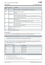
Illustration 108: Safety Relay with Plus and Minus Switching Output
Signals with test pulses must not have test pulses of >1 ms. Longer pulses may lead to reduced availability of the servo system.
8.6.1 Protective Measures
Install the ISD 510/DSD 510 system components with a protective rating of less than IP54 in an IP54 cabinet as per IEC 60529 or
in an equivalent environment. In special applications, higher IP protection may be necessary.
If external influences can affect the motor axis, for example suspended loads, use additional measures, such as a safety holding
brake, to eliminate hazards.
8.7 Application Example
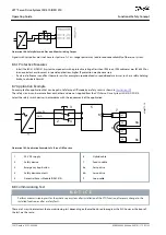
An example of an application that can be put in Safe Torque Off mode by a safety circuit is shown in
The safety circuits can be remote from each other and are not supplied from the VLT
®
Servo Drive System ISD 510/DSD 510.
Select the safety switch devices in accordance with the requirements of the application.
+24 VDC
GND
e
3
0
b
g
2
7
3
.1
0
8a
8b
5
3
4
2
1
X1
X2
X1
X2
9
7
6
Illustration 109: Application Example: Safe Torque Off Function
1
24 V DC supply
2
Safety device
3
Emergency stop button
4
Safety device contacts
5
Decentral Access Module (DAM 510)
6
Hybrid cable
7
Feed-in cable
8a
Servo drive
8b
Servo drive
9
Loop cable
8.8 Commissioning Test
N O T I C E
Perform a commissioning test for the whole servo system after installation of the STO function, after every change to the
installed function, or after a safety fault.
There are 2 ways to implement the commissioning test depending on the method used to program the PLC, however the steps of
the test are the same:
AQ262449648484en-000101 / 175R1135
150 | Danfoss A/S © 2020.08
Functional Safety Concept
VLT® Servo Drive System ISD 510/DSD 510
Operating Guide


