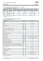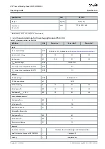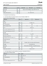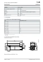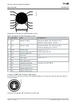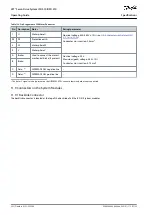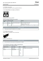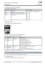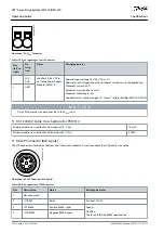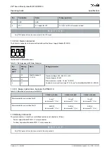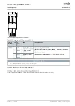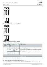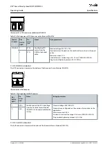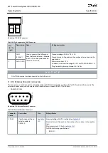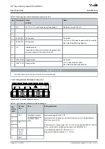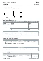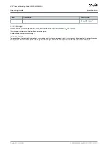
Table 133: Pin Assignment of X6 Motor Connector
Pin Description Notes
Rating/parameter
1
U
Motor phase U
Nominal voltage: 400–480 V ±10% (see
11.2.3 Characteristic Data for DSD
)
Conductor cross-section: 2.5 mm
2
PE
PE
Protective earth
3
W
Motor phase W
4
V
Motor phase V
A
Brake+
Used to connect the motor's
mechanical brake (if present).
Nominal voltage: 24 V
Maximum (peak) voltage: 48 V ±10%
Conductor cross-section: 0.75 mm
2
B
Brake–
C
Data–
(1)
HIPERFACE DSL negative line
–
D
Data+
(1)
HIPERFACE DSL positive line
–
1
The data+/– signals are only present on the HIPERFACE DSL variant, otherwise both are not connected.
11.9 Connectors on the System Modules
11.9.1 Backlink Connector
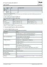
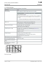
The backlink connector is located at the top of the backside of all the ISD 510 system modules.
AQ262449648484en-000101 / 175R1135
202 | Danfoss A/S © 2020.08
Specifications
VLT® Servo Drive System ISD 510/DSD 510
Operating Guide

