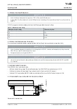
•
•
-
-
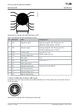
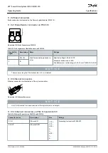
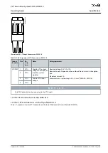
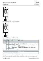
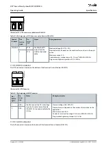
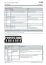
Pins
Description
Notes
Rating/parameter
5
GND
GND
–
6
VCC
5 V supply for LCP
5 V ±10% at 120 mA maximum load
N O T I C E
Only PELV potential can be connected to the LCP input.
11.9.7 AC Mains Connector
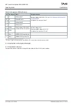
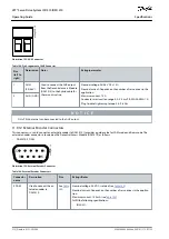
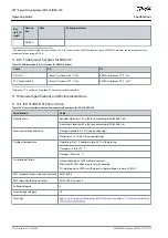
The AC mains connector is located on the bottom of the Power Supply Module (PSM 510).
e
3
0
b
g
4
5
2
.1
0
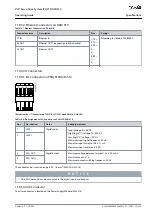
Illustration 147: AC Mains Connector
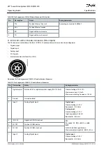
Table 141: Pin Assignment of AC Mains Connector
Pins
(left to
right)
Descrip-
tion
Notes
Rating/parameter
1
L3
Used to connect
L1/L2/L3
Nominal voltage: 400–480 V AC ±10%
Nominal power: 30 kW
Maximum cross-section: 16 mm
2
(AWG 4)
Conductor cross-section range 0.75–16 mm
2
, solid or flexible (AWG 18–AWG 4)
2
L2
3
L1
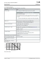
11.9.7.1 Mains Cable Cross-Sections for PSM 510
Table 142: Mains Cable Cross-Sections for PSM 510
PSM 510 (10 kW)
PSM 510 (20 kW)
PSM 510 (30 kW)
Minimum cable cross-section for CE
4 mm
2
(minimum 70 °C, Cu)
16 mm
2
(minimum 70 °C, Cu)
16 mm
2
(minimum 90 °C, Cu)
Minimum cable cross-section for UL
AWG 10
(minimum 60 °C, Cu)
AWG 6
(minimum 60 °C, Cu)
AWG 4
(minimum 75 °C, Cu)
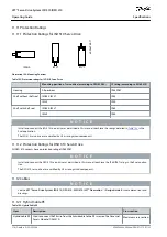
11.9.8 Relay Connector
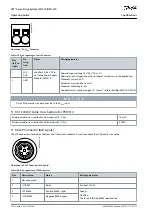
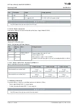
The relay connector is used for a user-defined reaction and is located as follows:
Power Supply Module PSM 510: 1 relay connector
Auxiliary Capacitors Module ACM 510: 1 relay connector
N O T I C E
Only PELV potential can be connected to the relay outputs.
AQ262449648484en-000101 / 175R1135 | 207
Danfoss A/S © 2020.08
Specifications
VLT® Servo Drive System ISD 510/DSD 510
Operating Guide

