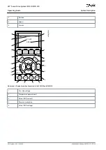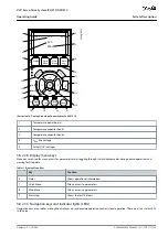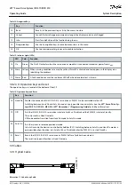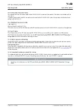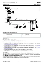
Table 12: Navigation Keys
Key
Function
10
Back
Reverts to the previous step or list in the menu structure.
11
Cancel
Cancels the last change or command as long as the display mode is not changed.
12
Info
Press for a definition of the function being shown.
13
Navigation keys
Use the 4 navigation keys to move between items in the menu.
14
OK
Use to access parameter groups or to enable a selection.
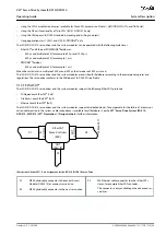
Table 13: Indicator Lights (LEDs)
LED
Color
Function
15 On
Green
The
On
LED activates when the servo drive or module it is connected to receives power from U
AUX
.
16 Warn
Yellow When warning conditions are met, the yellow
Warn
LED activated and text appears in the display area
identifying the problem.
17 Alarm Red
A fault condition causes the red
Alarm
LED to flash and an alarm text is shown.
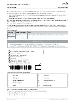
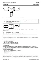
3.8.2.4 D: Operation keys and reset
The operation keys are located at the bottom of the LCP.
Table 14: Operation Keys and Reset
Key
Function
18 Hand On Enables the connected ISD 510/DSD 510 servo drive or PSM 510 to be controlled via the LCP.
Switching between
Hand On
and
Auto On
modes is only possible in certain states (see the
VLT® Servo Drive Sys-
tem ISD 510, DSD 510, MSD 510 (VLT® Flexmotion
™
) Programming Guide
for further information).
19 Off
Puts the ISD 510/DSD 510 servo drive into state
Switch on Disabled
and the PSM 510 into state
Standby
.
This only works in
Hand On
mode.
Off
mode enables transition from
Hand On
mode to
Auto On
mode.
20 Auto On
Puts the system in remote operational mode.
In
Auto On
mode, the device is controlled by fieldbus (PLC). Switching between
Auto On
and
Hand On
modes is
only possible when the drive is in state
Switch on Disabled
and/or the PSM 510 is in state
Standby
.
21 Reset
Resets the ISD 510/DSD 510 servo drive or PSM 510 after a fault has been cleared.
The reset is only possible when in
Hand On
mode.
3.9 Cables
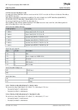
3.9.1 Hybrid Cable
e
3
0
b
e
3
8
3
.1
1
Illustration 11: Hybrid Loop Cable
AQ262449648484en-000101 / 175R1135
40 | Danfoss A/S © 2020.08
System Description
VLT® Servo Drive System ISD 510/DSD 510
Operating Guide


