•
•
•
•
•
•
•
•
•
-
-
-
-
-
-
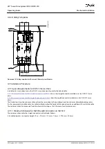
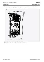
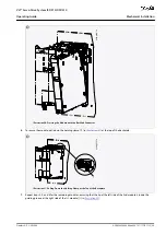
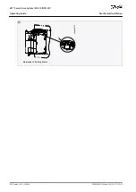
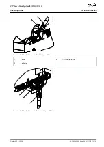
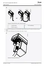
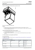
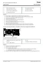
1
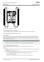
Cable tie
2
EMC metal shielding plate
3
PE screw
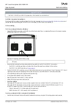
Use a cable with a shielding that has a high-coverage to reduce electrical interference.
Do not use pigtails to connect the shielding. A 360° wire connection is recommended.
N O T I C E
POTENTIAL EQUALIZATION
There is a risk of electrical interference when the ground potential between the servo system and the machine is different.
Install equalizing cables between them. The recommended cable cross-section is 16 mm
2
.
N O T I C E
EMC INTERFERENCE
Use shielded cables for control wiring and separate cables for power and control wiring. Failure to isolate power and control
wiring can result in unintended behavior or reduced performance.
Ensure a minimum clearance of 200 mm between signal and power cables.
Only cross cables at 90°.
5.5 Mains Supply Requirements
Ensure that the supply has the following properties:
TN-S, TN-C, TN-CS, TT (not corner earthed) supply earthing system.
Prospective short-circuit current: 5 kA.
Protective class I.
Grounded 3-phase mains network, 400–480 V AC ±10%.
3-phase lines and PE line.
3-phase frequency: 44–66 Hz
Maximum input current for 1 PSM 510 at 30 kW: 55 A
rms
5.5.1 Fuses
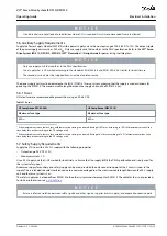
N O T I C E
Use fuses on the supply side of the Power Supply Module PSM 510 that comply with CE and UL requirements (see
).
When 2 PSM 510 modules are used, each PSM 510 must have its own dedicated set of fuses.
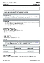
Table 20: Fuses
Model and power rating
CE Compliance (IEC 60364)
UL Compliance (NEC 2014)
Maximum fuse type
Maximum fuse type
PSM 510 (10 kW)
gG 25 A
30 A (class T or J only)
PSM 510 (20 kW)
gG 50 A
50 A (class T or J only)
PSM 510 (30 kW)
gG 63 A
80 A (class T or J only)
5.5.2 Circuit Breakers
Use a type B or type C circuit breaker with a capacity of 1.5 times the rated current of PSM 510 to fulfill CE requirements.
AQ262449648484en-000101 / 175R1135
64 | Danfoss A/S © 2020.08
Electrical Installation
VLT® Servo Drive System ISD 510/DSD 510
Operating Guide

