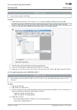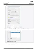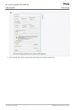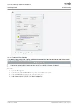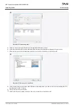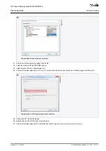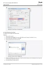
1.
-
2.
3.
4.
5.
6.
•
•
•
•
•
•
•
•
•
-
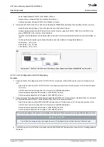
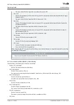
Depending on the mode of operation to be used, select either the slot
CSP PDO
or
CSV PDO
. Per default,
CSV PDO
is mapped
and pre-selected. Map the following variables if the VLT® Integrated Servo Drive servo drive is required to work with CSP
PDO:
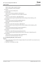
In the
Settings
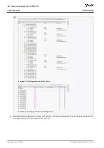
Tab of the NC Axis, select [NC-Configuration
→
NC-Task 1 SAF
→
Axes
→
Axis 1]. Click on the
Link To (all
Types)...
button and select the desired servo drive.
In the same tab, select the preferred
Unit
.
Depending on the selected unit, adjust the
Scaling Factor
for the axis encoder via menu [NC-Configuration
→
NC-Task 1 SAF
→
Axes
→
Axis 1
→
Axis 1_Enc] in the
Parameter
tab. Example: When the unit
Degrees
is selected, the scaling factor is
360°/2
20
= 0.00034332275390625.
Set the
Reference Velocity
in the
Parameter
tab via menu [NC-Configuration
→
NC-Task 1 SAF
→
Axes
→
Axis 1
→
Axis
1_Enc.
Set the
Output Scaling Factor
(Velocity) to 125.
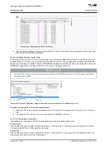
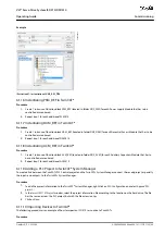
Test the functionality and the configuration in the
Online
tab of the axis.
6.11.16 Connecting to the PLC
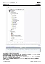
Information on how to connect to the PLC can be found in detail in the Beckhoff Information System .
Open the information system and go to [TwinCAT 2
→
TwinCAT System Manager
→
Operation
→
Controls
→
Choose Target Sys-
tem].
6.12 Programming Guidelines for Automation Studio™ and TwinCAT®
Recommendations for implementation:
Initialize parameters that usually do not change only once at the beginning of the program. In Automation Studio
™
, use the
_INIT
section.
Call up function blocks that provide status or error information with
Enable
input at the beginning of the program.
Use 1 instance of the function block
MC_Power_DDS
for every axis to control its power stage. Call up this function block in every
PLC cycle.
Use 1 instance of the function block
DD_Power_PSM
for every PSM 510 to control the DC-link voltage on the output. Call up this
function block in every PLC cycle.
Use 1 instance of the function block
DD_Power_DAM
for every DAM 510 to control the DC-link voltage on the output. Call up
this function block in every PLC cycle.
Use 1 instance of the function block
DD_Power_ACM
for every ACM 510 to control the connection between the DC-link and the
ACM 510. Call up this function block in every PLC cycle.
Call up function blocks that execute (motion) commands at the end of the program.
Do not use any POUs from the library (folder)
DDS_Intern
.
Do not change the reference to the axis on a function block while it is busy.
N O T I C E
The full parameter list can be found in the
VLT® Servo Drive System ISD 510, DSD 510, MSD 510 (VLT® Flexmotion
™
) Pro-
gramming Guide
.
6.13 Programming with SIMOTION SCOUT®
6.13.1 Requirements for Programming with SIMOTION SCOUT®
The following files are required to integrate the servo system modules into a SIMOTION SCOUT
®
project. In the filename,
2.xx
repre-
sents the version number and
yyyymmdd
represents the date.
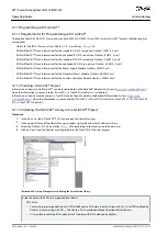
Table 26: Required Files
System Module
File required
Whole servo system
Package of libraries for the ISD 510 servo system: Danfoss_VLT_ServoMotion_V_x_y_z.zip
Online Help file(.chm): Programming with SIMOTION SCOUT
®
AQ262449648484en-000101 / 175R1135
106 | Danfoss A/S © 2020.08
Commissioning
VLT® Servo Drive System ISD 510/DSD 510
Operating Guide


