1.
2.
3.
-
-
-
-
60
[2.36]
60
[2.36]
101
[3.98]
106
[4.17]
e
3
0
b
g
8
2
1
.1
0
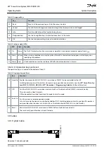
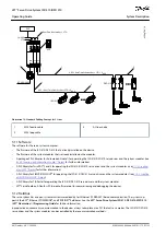
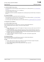
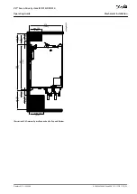
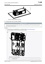
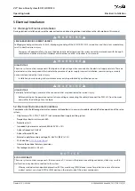
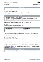
Illustration 24: Minimum Space Required at the Sides
4.7.4 Installation Aids and Tools Required
For installation of the ISD 510 servo drives, the tools corresponding to the fixings screws (not included) are required.
4.7.5 Fitting Instructions for ISD 510 Servo Drive
4.7.5.1 Overview
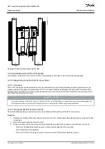
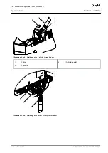
The ISD 510 servo drives are delivered with an M23 transport protection cap. The M23 blind cap used for IP protection must be
ordered separately. The advanced version of the ISD 510 servo drive is delivered additionally with M8 and M12 blind caps. These
blind caps prevent contamination of the servo drive and are necessary to achieve the relevant IP protection rating. Always mount
these caps if the connector is not used.
N O T I C E
Ensure the machine surface that comes in contact with the servo drive flange is unpainted in order to guarantee good ther-
mal behavior of the servo drive. The surface contact must also provide sufficient grounding protection.
4.7.5.2 Clamping the ISD 510 Servo Drive
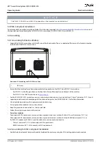
Observe the following fitting instructions to ensure the reliable and effective fitting of the ISD 510 servo drive.
Procedure
Check the counterface of the motor mount and ensure that it has sufficient heat dispersion capacity. An unpainted surface
is mandatory.
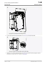
Remove the protective end cap from the shaft.
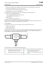
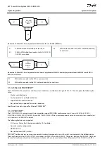
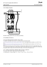
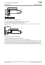
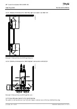
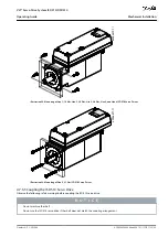
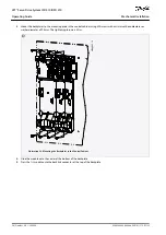
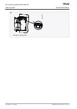
Fix the servo drive with 4 screws using the 4 mounting holes provided for this purpose in the machine unit as shown.
Always use the designated mounting holes in the mounting flange to fix the servo drive.
Do not modify the mounting holes.
Always use all 4 mounting holes. The motor may run unevenly if fewer mounting holes are used.
AQ262449648484en-000101 / 175R1135
54 | Danfoss A/S © 2020.08
Mechanical Installation
VLT® Servo Drive System ISD 510/DSD 510
Operating Guide

