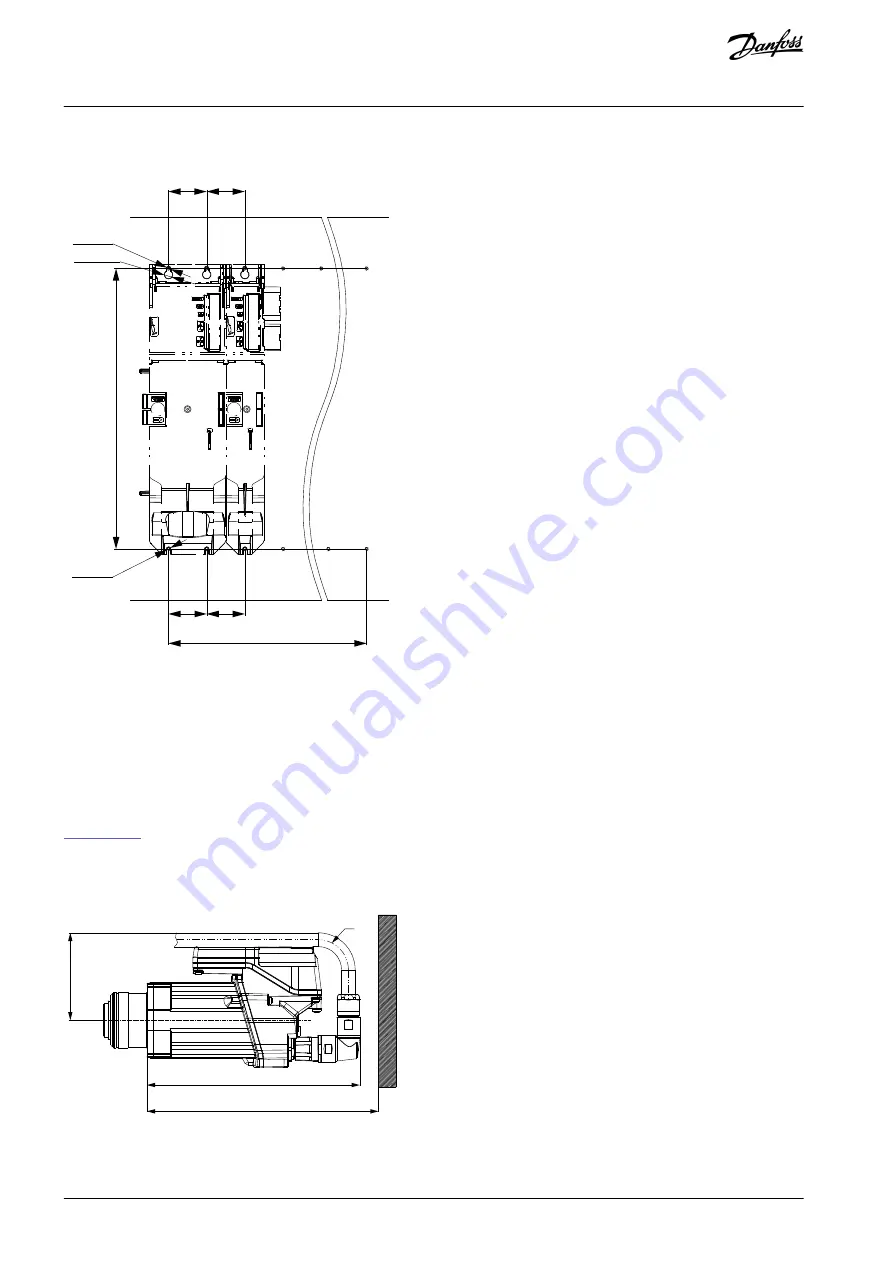
4.6.3 Drilling Templates
(100 x number of FS2 + 50 x number of FS1) - 50
FS2
FS1
50
50
[1.97]
[0.42]
[14.45]
[1.97]
50
50
[1.97]
[1.97]
M5
M5
367
UNF 10-32
UNF 10-32
Ø10,6
e30bg819.10
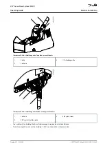
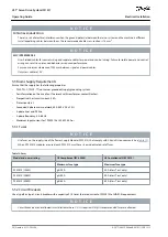
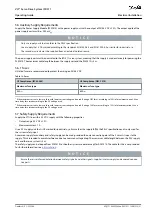
Illustration 9: Drilling templates for 50 mm and 100 mm System Modules
4.7 Installation Procedure
4.7.1 Space Requirements for ISD 511
In addition to its own dimensions, the ISD 511 servo drive needs space for the hybrid cable and the connector.
4.7.1.1 Minimum Distance for M23 Angled Connector
shows the minimum distance from the servo drive to the next object.
For cable installation (connecting/disconnecting the M23 angled connector on an installed device), allow a mounting space of the
height of the connector plus an additional 25 mm (273 mm – 248 mm).
The minimum bending radius R
min
for permanently static installed cable is 22.5 mm.
R35
102
248
273
e30bk208.10
Illustration 10: Minimum Distance for M23 Angled Connector
AQ377148425069en-000101
/ 130R1213
36 | Danfoss A/S © 2023.08
Mechanical Installation
VLT® Servo Drive System ISD 511
Operating Guide


