-
-
-
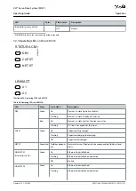
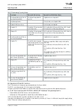
Abbrevia-
tion
Reference
Description
Unit: years
PFH
EN IEC 61508
Probability of dangerous failures per hour
Take this value into account if the safety device is operated in high demand mode or in contin-
uous operating mode, where the frequency of demands for operation made on a safety-rela-
ted system occurs more than once per year.
PL
EN ISO 13849-1
Performance level
A discrete level used to specify the capability of safety-related parts of a system to perform
safety-oriented functions under foreseeable conditions. Levels: a–e.
SFF
EN IEC 61508
Safe failure fraction [%]
Proportion of safe failures and detected dangerous failures of a safety function or a subsystem
as a percentage of all possible failures.
SIL
EN IEC 61508
EN IEC 62061
Safety integrity level
STO
EN IEC 61800-5-2 Safe Torque Off
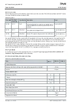
8.6 Installation
Only Danfoss cables can be used for the installation of the servo system, however cables from other suppliers can be used for the
user connection to the STO terminal
STO DAM (Pins 3 and 4)
on the Decentral Access Module (DAM 510).
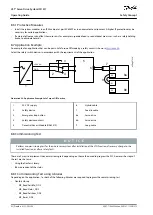
Safety relays that have a plus and minus switching output signal can be directly connected to the servo system to activate STO.
The example in
not supplied by Danfoss. The STO is activated by opening STO+ and STO–.
Table 22: Activation of STO Function
STO+
STO–
STO function
24 V
GND
STO deactivated
Open
GND
STO activated
24 V
Open
STO activated
Open
Open
STO activated
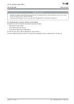
N O T I C E
Do not exceed 30 V at the STO inputs.
STO is activated if the plus input is between –3 V and +3 V.
STO is deactivated if the plus input is b21.6 V and +26.4 V.
Illustration 55: Safety Relay with Plus and Minus Switching Output
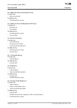
Signals with test pulses must not have test pulses of >1 ms. Longer pulses may lead to reduced availability of the servo system.
AQ377148425069en-000101
/ 130R1213 | 91
Danfoss A/S © 2023.08
Safety Concept
VLT® Servo Drive System ISD 511
Operating Guide

