5.
1.
2.
3.
4.
5.
6.
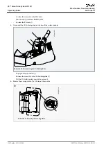
1.
-
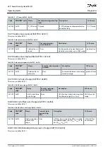
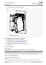
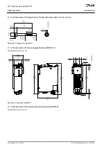
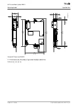
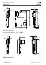
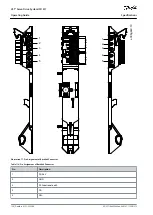
Tilt the module forward and remove it from the backplate.
X2
e30bg816.10
STATUS PSM
DEV
SVS ST
NET ST
LINK/ACT
LIN
S
X2
LCP
STATUS DAM
DEV
SVS ST
NET ST
AUX
LINK/ACT
X1
X1
X
X2
X3
X3
LCP
Illustration 60: Removing the Module
10.5.2 Fitting and Commissioning the System Modules
Check if preparation is required (see
).
Fit the system modules (see
4.7.5 Fitting Instructions for System Modules
Connect the electrical cables (see chapter
Electrical Installation
).
6.2 Switching on the ISD 511 System
).
Configure the system module's parameters according to the fieldbus used.
Conduct a test run.
10.6 Cable Replacement
10.6.1 Overview
Replace the cables when the rated number of bending cycles has been reached or the cable is damaged.
N O T I C E
Do not forcefully connect or fit the connectors. Incorrect connection causes permanent damage to the connectors.
10.6.2 Feed-In Cable Replacement
10.6.2.1 Disconnecting the Feed-In Cable
Procedure
Disconnect the Power Supply Module (PSM 510) from its power source (mains network and all auxiliary supplies).
AQ377148425069en-000101
/ 130R1213 | 121
Danfoss A/S © 2023.08
Maintenance, Decommissioning
and Disposal
VLT® Servo Drive System ISD 511
Operating Guide

