21. In the
Attach Variable port (Input)
window, select [PLC-Configuration
→
MyFirstIsd510Project
→
Standard
→
.myAxis.NodeNumber].
22. Click on
OK
.
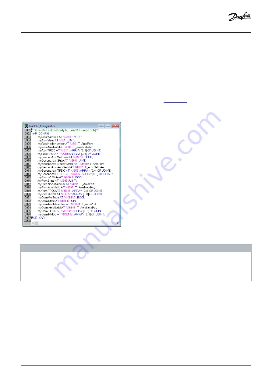
6.12.13 Transferring the Mappings back to the PLC Program
To transfer the mappings back to the PLC program, select
Activate Configuration...
in menu item
Actions
.
After a rebuild in TwinCAT
®
PLC Control, the TwinCAT
®
(here
myAxis
and
mySecondAxis
are
instances of
AXIS_REF_DDS
,
myPSM
is an instance of
PSM_REF
, and
myDAM
is an instance of
DAM_REF
). The concrete addresses can be
different.
e3
0b
h5
20
.1
0
Illustration 79: TwinCAT
®
Configuration: I/O Mapping of 2 Servo Drives, 1 PSM 510, and 1 DAM 510
NOTICE
-
Connect the PSM 510, DAM 510, ACM 510, and SDM 511/SDM 512 to 1 SYNC unit and the ISD 510/DSD 510 servo drives to
another. This protects against interruptions in communication to the PSM 510 and DAM 510 if the U
AUX
supply to the
decentral servo drives is switched off due to an error.
6.12.14 Setting the PLC Cycle Time in TwinCAT® PLC Control
Context:
The minimum cycle time is 400 µs. The MSD 510 devices can run EtherCAT
®
cycle times in multiples of 400 µs or 500 µs. The devices are
automatically parameterized by the PLC on start-up, depending on the EtherCAT
®
configuration of the physical interface. To access the
system base time, select [SYSTEM-Configuration
→
Real-Time Settings] in the TwinCAT
®
System Manager. Multiples of this base time
can then be used as EtherCAT
®
cycle times.
Commissioning
Operating Guide | VLT® Multiaxis Servo Drive MSD 510 System
AQ262450196490en-000101 / 175R1170
110 | Danfoss A/S © 2019.10
Summary of Contents for VLT MSD 510
Page 1: ...Operating Guide VLT Multiaxis Servo Drive MSD 510 System...
Page 2: ......


