21
21
Danfoss District Energy
VI.GP.P1.02
DKDHR
Instructions
VX Solo II
7.0 Mounting
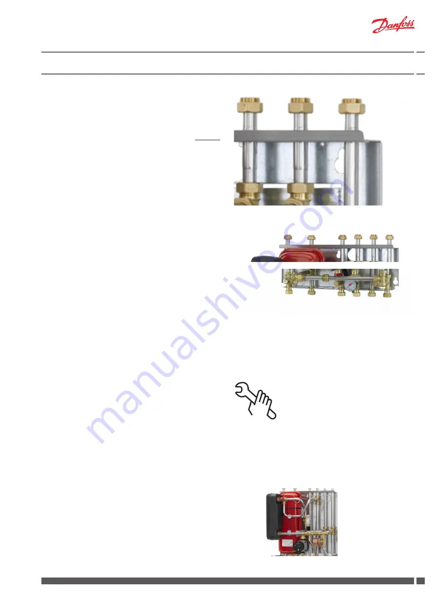
7.1 Variable connection possibilities
The substations offer variable connection possibilities (not VX Solo
II HWS OP), as connection of pipes can be established in the top
or in the bottom of the substation. Upon delivery the substation is
prepared for connection in bottom of the substation.
For change of connection from bottom to top, demount plugs on
connection pipes in top of substation and ball valves on connection
pipes in bottom of substation, and mount plugs in connection pipes
in bottom of substation and ball valves on connection pipes in top
of substation.
Please note that the air screw, which originally is mounted on the
heating supply pipe in top of substation must be relocated to the
highest point of the substation.PLEASE NOTE that the variable con-
nection possibilities makes it possible to establish some of the con-
nections in the top and
others in the bottom of the substation. This may be desirable in some
cases.
7.2 Tightening of connections
Check and tighten all connections before adding water to the system,
as vibrations during transport may have caused leaks.
After having added water to the system, tighten all the connections
before performing leak test. If the substation operates in accordance
with the dimensioning basis, re-tighten the connections and take the
substation into continuous use.
Please note that the connections may be supplied with EPDM rub-
ber gaskets - in general connection sizes from ¾” to and incl. 1½”
for Kompakt H stations. Therefore take care not to overstrain the
union nuts, as this may result in leaks. The manufacturer accepts
no liability for leaks that result from overstrain of union nuts.
7.3 Expansion vessel
The VX Solo II substations are equipped with an expansion vessel,
which is factory set to 0,5 bar.
Please note that for type HWS OP the expansion vessel is not part
of the delivery.
Necessary assembly, start-up and maintenance work must be per-
formed by qualified and authorized personnel only, and always in
compliance with local regulations and this instruction manual.
The substation must be easily accessible, enabling maintenance
work without undue discomfort.
The substation is intended for wall mounting and the mounting
sheet on the back of the substation has got holes for screw instal-
lation. Lift the substation in the back plate and fix it to a solid wall,
which has the necessary load-bearing capacity, in a workmanlike
manner with two strong bolts, screws or expansion plugs.
All pipes and connections must be cleaned and rinsed before start-
up. After that the strainers should be cleaned.
A label for each of the different connections is placed on the substa-
tion. Connect the substation to the household piping according to
these symbols as well as the instructions in this manual.


