MAGNET POWER SUPPLY SYSTEM 7000
8
DANFYSIK A/S - DK 4040 JYLLINGE - DENMARK.
2.6
Master/ Slave configuration (two or more unit in parallel)
•
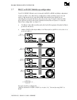
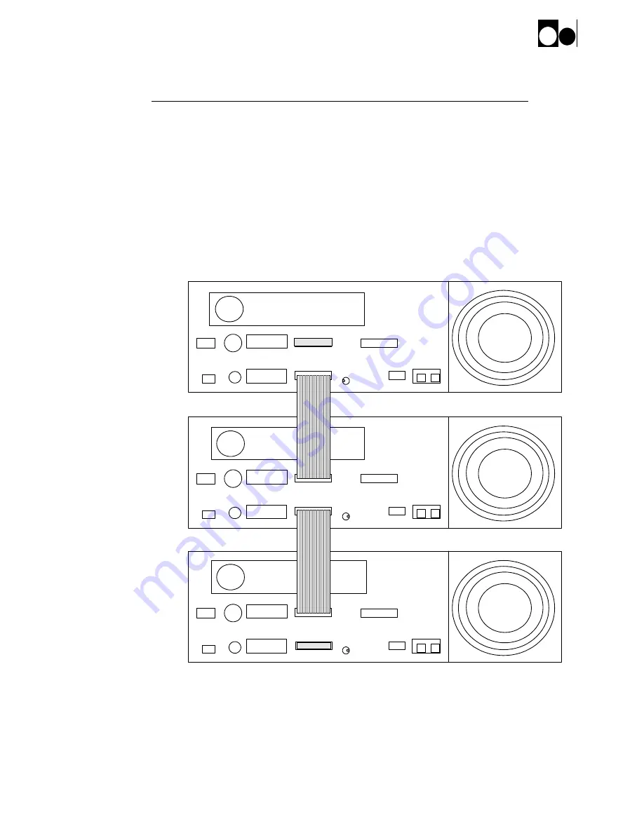
The Master / Slave slide switch located on the back of the supply must be placed in Master
position for the master unit and in slave position for all the other units. Only one SYSTEM
7000 must be configured as master.
•
Connect the “Parallel unit” interface cable between the “Parallel unit to slave” DB25 male
plug of the first unit (normal master) to the “Parallel unit to master” DB25 female plug of
the next unit and so on in a daisy chain. The first unit must have the termination plug
connected to the “Parallel unit to master” and the last unit must have the termination plug
connected to the “Parallel unit to slave”.
•
Not used external interlocks must be short-circuited.
Analog
Parallel units
to slaves
Parallel units
to master
External Interlocks
Digital
AC Main Power
External trig
Factory Program
MPS status
Current
Output
Ground
fuse
Ac control input
Rack Fan
Analog
Parallel units
to slaves
External Interlocks
Digital
AC Main Power
External trig
Factory Program
MPS status
Current
Output
Ground
fuse
Ac control input
Rack Fan
Analog
Parallel units
to slaves
External Interlocks
Digital
AC Main Power
External trig
Factory Program
MPS status
Current
Output
Ground
fuse
Ac control input
Rack Fan
Parallel units
to master
Parallel units
to master
Master Slave
Master Slave
Master Slave
Master
Slave
Slave
Termination plug
Example of a Master/Slave configuration with two slaves


