MAGNET POWER SUPPLY SYSTEM 7000
10
DANFYSIK A/S - DK 4040 JYLLINGE - DENMARK.
3
Operating Instructions
This chapter describes how to operate the power supply in the local as well as in the remote
mode. It also identifies the controls and the indicators on the front panel.
3.1
Switching on
After connecting the Power Supply to the mains (line) voltage in accordance with chapter 1.2,
2.3 and 2.4, it can be switched ON.
_
Switch the main power ON
_
Set control mode to LOCAL
_
If the sum Interlock indication is set (red LED illuminates in the RESET button), press
this button to clear it. If it can’t be cleared, interlocks are present and must first be
resolved.
3.2
Main power ON, OFF, STB & Reset
The power supply can be set to three different modes for turning the power supply ON and
OFF given as below.
0)
Direct ON & OFF (default mode)
1)
Standby mode 1
2)
Standby mode 2
The desired working mode can be selected using the ‘esc’<NFSMODE command. See the
software description for setting up the power supply and for further detail of this issue.
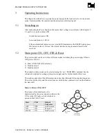
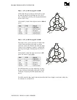
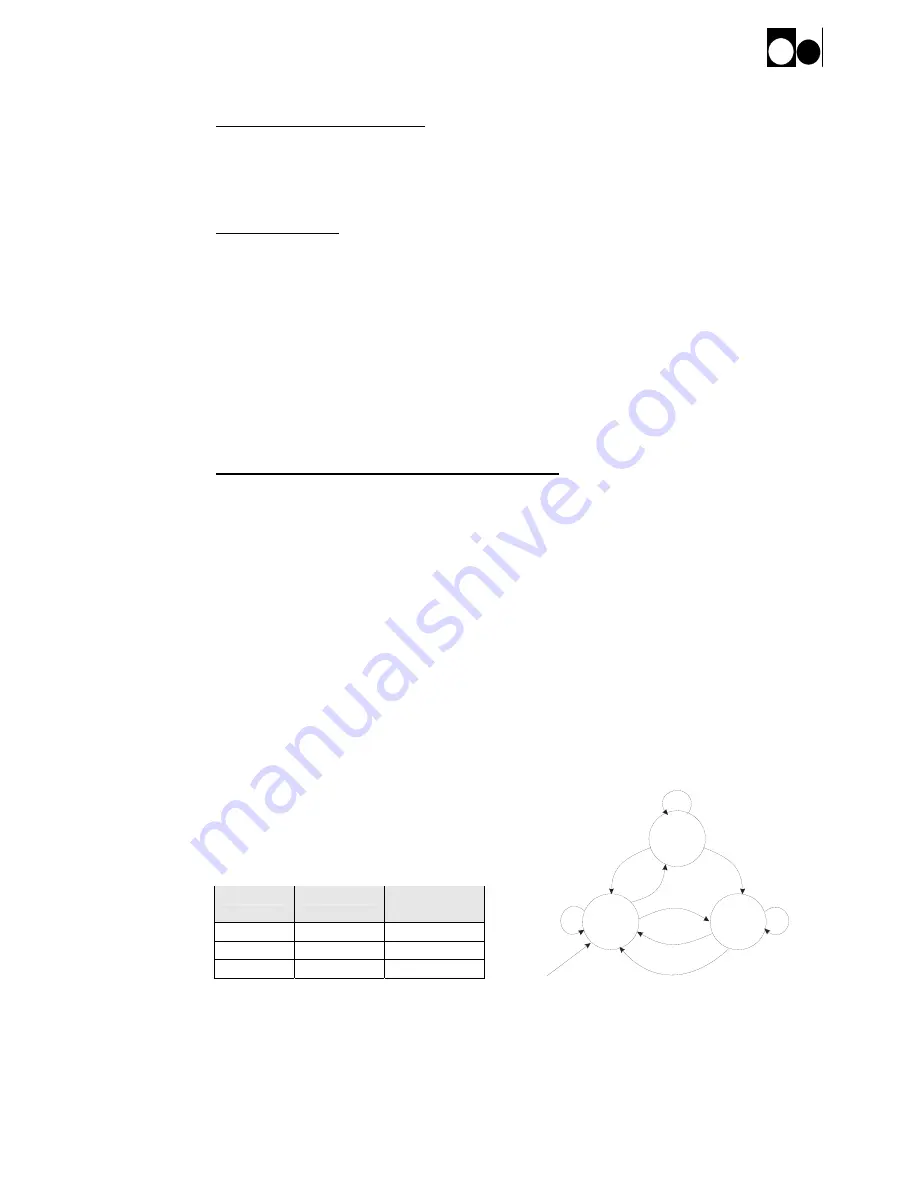
The working principle of the different modes is described through following state diagrams.
The circles are the state and the arrow lines are witch button, command or event that initiates
the state shift.
Mode 0 – Direct ON & OFF
This mode is the default mode. It is
characterized by the power supply is either in the
ON or in the OFF state or if an interlock is
present in the FAULT state.
State
FAN
Output
Converter
OFF OFF Not
Powered
ON ON Powered
FAULT ON
Not
Powered
ON-S
INTL
ON
OFF
OFF-S
AC Power
ON
RESET
FAULT
RES
{no INTL}
INTL
{event}
Else
Else
OFF
Off = Reset}
{no INTL &


