MAGNET POWER SUPPLY SYSTEM 7000
25
DANFYSIK A/S - DK 4040 JYLLINGE - DENMARK.
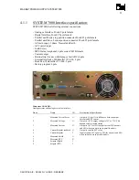
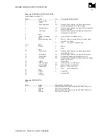
Connector PARALLEL UNITS TO SLAVES:
Parallel hardware control P111
Pin no:
Name
I/O
Description & Specification
1
-Power is ON
I
2 -15VD O
3
/Out of regulation
I/O
Interlock Open collector, low when output current
exceeds the limit of 2,5% of the set value
4
/Summary fault
I/O
Interlock Open collector, low when SCR in Start/Stop
control is activated.
5
/Over temp
I/O
Interlock Open collector, low when the heat-sink of
the amplifier is above 80°C
6 Spare
7
/Standby command
I/O
Open collector, low Standby pulse.
8 Spare
9
Summed current error
I
Master : Converts current into error voltage signal
scaled by no of units.
O
Slave : 1 mA per 2% error per unit
10-11 Spare
12 Setpoint O
Master
I
Slave
13 Spare
14
/Over current
I/O
Interlock Open collector, low when output current
reach adjusted level
15
/PS fan fault
I/O
Interlock Open collector, low when inside fan fail.
16
/Ground fault
I/O
Ground fault automatically disabled in slaves
17
/AC fault
I/O
Interlock Open collector, low when one of the voltage
supply lines are low.
18
GND D
Digital GND
19
/OFF command
I/O
Open collector, low OFF pulse
20
/ON command
I/O
Open collector, low ON pulse
21
Unit parallel
I
Master : X mA = X slaves.
O
Slave : 1 mA sink per unit
22 Spare
23
GND A
I
Loop GND
24
GND A
Analog GND
25 Not
used
Connector MPS STATUS:
P103
Pin no:
Name
Description & Specification
1
MPS
This pin is conncted to pin 3 when the SYSTEM 7000 is ON.
2
PIN2&4
Pin 2 and 4 is connected
3
MPS
This pin is conncted to pin 1 when the SYSTEM 7000 is ON.
4
PIN2&4
Pin 2 and 4 is connected

