MAGNET POWER SUPPLY SYSTEM 7000
28
DANFYSIK A/S - DK 4040 JYLLINGE - DENMARK.
4.2.4
Slow ADC circuit
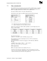
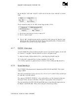
Different voltages are monitored by means of the Analog to Digital converter U19. The
measured values and their resolution are shown in the table below.
The 2.5V reference voltage for the ADC converter comes from U25.
The following analogue signals are monitored:
VALUE
BIT
RESOLUTION
Output current
17 + sign
Current Limit
17 + sign
Output Voltage
17 + sign
Voltage Limit
17 + sign
Voltage reference
17 + sign
4.2.5
Voltage reference
The voltage reference circuit is constructed around U25 “MAX6350” which delivers a 5V high
precision voltage to the ADC “U19” and the DAC “U1 & U10”.
4.2.6
Fast ADC for reading/displaying of output current
From PCB revision B
The ADC U19 has a sample rate of 1 second. If a faster sample rate is required, the fast ADC
circuit can be selected by inserting strap ST11. The fast ADC is capable of converting the
output current up to 30 times a second with a resolution of 12 bit + sign. The sampling may be
synchronized from an external trig signals SYNC+I and SYNC-I on connector X6. For
enabling the external ADC trig, pin 16 on connector X7 need to be set low (high-to-low
transition) otherwise the fast ADC will run continuously at highest speed.
The fast ADC circuit is built around A4A and A4B together with two of the CPU internal ADC
channels in an average over sampling technique.
The sampling frequency of these two channels is 10 kHz each, but due to the running average
calculation, to achieve the 12 bit accuracy from the 10 bit internal ADC, is the practice
sampling rate reduced to 30Hz.
The sign for the fast ADC reading is built around a comparator LM311.

