MAGNET POWER SUPPLY SYSTEM 7000
30
DANFYSIK A/S - DK 4040 JYLLINGE - DENMARK.
4.2.9
Front Panel Interface specification:
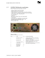
The Front Panel has following connection:
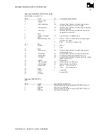
Connector X1:
(Analog signals To/From the Front Panel)
Pin no: Name
I/O
Description & Specification
1
Local Reference
O
0 - ±10VDC from DAC circuit in Front Panel
2
Current Limit
O
0 - +10VDC from current limit potentiometer.
3
Voltage Measured
I
0 - ±10VDC to BNC connector in Front Panel
4
Current Measured
I
0 - ±10VDC to BNC connector in Front Panel
5
Current Setpoint
I
0 - ±10VDC to BNC connector in Front Panel
6
Number of units in parallel
I
1-7VDC to ADC in Front Panel
7-10 Spare
11-12 +15V
I
13-14 -15V
I
15-16 GNDA
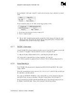
Connector X4:
(Digital signals To/From the Front Panel)
Pin no: Name
I/O
Description & Specification
1
Local, /Remote
O
Signal from
:
-
Processor 0V=Remote, 5V=Local
2
/OFF Local
O
Active low signal from push button in Front Panel
3
OFF status
I
5V to OFF status LED
4
/Standby,/Reset
O
Active low signal from push button in Front Panel
5
Standby status
I
5V to Standby status LED
6
/ON Local
O
Active low signal from push button in Front Panel
7
ON status
I
5V to ON status LED
8
Over Current Interlock
I
5V to Over Current Interlock LED
9
Over Voltage Interlock
I
5V to Over Voltage Interlock LED
10
Over Temperature Interlock
I
5V toOver Temperature Interlock LED
11
PS Fan Fault Interlock
I
5V to PS Fan Fault Interlock LED
12
Out of Regulation Interlock
I
5V to Out of Regulation Interlock LED
13
Ground Fault Interlock
I
5V to Ground Fault Interlock LED
14
AC Fault Interlock
I
5V to AC Fault Interlock LED
15
Summary Interlock
I
5V to Summary Interlock LED
16
Magnet Over Temperature Interlock I
5V to External Magnet Over Temperature Interlock LED
17
Rack Airflow Interlock
I
5V to External Rack Airflow Interlock LED
18
Spare 1
I
5V to External Spare 1 Interlock LED
19
Spare 2
I
5V to External Spare 2 Interlock LED
20
In Current Limit
I
5V to In Current Limit LED
21
Converter Over Voltage Interlock
I
5V to Converter Over Voltage Interlock LED
22
Master, /Slave
I
Display in Front panel is off in Slave mode. 5V=Master,
0V=Slave
23 75V,
/35V
I
:
-
Processor is scaling Voltage Display to 35V or 75V.
5V=75V, 0V=35V
24
Unit0
O
Unit 0-2 is 3 bit showing no of units in parallel.
25
Unit1
O
The 3 bit scales the summed regulation error to 2%=10V.
26
Unit2
O
The 3 bit scales the measured current to 100%=10V.
27-28 B+5V
I
29-30 GNDD
31-34
+15VUREG
I
Supply For DC/DC Converter
35-40 GNDUREG
I

