background image

MAGNET POWER SUPPLY SYSTEM 7000 


38


DANFYSIK A/S - DK 4040 JYLLINGE - DENMARK.                                                      

4.3.18


Current Regulation 


The ERROR amplifier U301A amplifies the ERROR signal from the summing point. 
 
The output current is converted to 0.1 ampere in the DCCT and it is measured as a voltage 
across the high precision, very low drift 10 

S

 burden resistor. This voltage is converted to a 

current using the resistors R304. This negative current is then compared with the positive 
current in a sum point, and the difference is fed to the amplifier U301 an LT1112. The 
amplification factor of U301 and its frequency response can vary with the specification for 
each power supply.  
 
The main task of the Regulation circuitry is to produce a regulated signal to the power output 
stage from the "ERROR" amplifier.  
 
The Regulation circuit contains the following main functions: 

 Current loop Amplifiers/compensation 

 Current Error Amplifier 

 
Due to the output load DCCT compensation, is it possible to connect many different loads to 
the output terminals of the power supply still keeping the regulation loop stable.  On special 
requirement and loads, fine tune some loop components are necessary. Please see the change 
notes in chapter 8 for possible change in component values. 
 
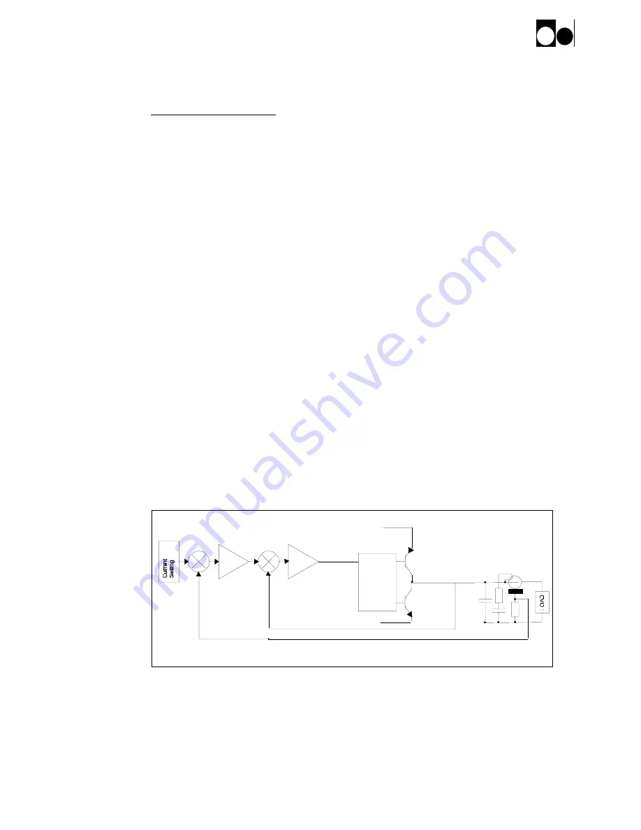
The regulation principle can easiest be illustrated by looking at the two major criteria for the 
loop. 


1- Inner loop for Power Amplifier 


2- Outer loop for ppm stabilisation. 


+ Out

Regulation principle for MPS SYSTEM 7000

Power Amplifier

DCCT Filter

PNP

Outer LOOP


A1


DCCT 1

+


-

+


-

Inner LOOP

A2

NPN

Driver

The figure shows the Principia of the two-loop regulation. 

Summary of Contents for SYSTEM 7000

Page 1: ...al OUTPUT DATA 20A 35V or 75V INTERFACE FRS232 FRS422 FRS485 REV By Date Description Pages 1 0 DT 09 06 2004 Initial All 1 1 DT 12 07 2004 Fast ADC and hardware triggering 28 29 1 2 DT 15 03 2005 Partial reset to factory settings 15 1 3 JFL 22 11 2005 Minor corrections All 1 4 JFL 18 10 2006 Minor corrections 415 added All M A N U A L MAGNET POWER SUPPLY SYSTEM 7000 DANFYSIK A S DK 4040 Jyllinge D...

Page 2: ... This documentation contains information which is the property of DANFYSIK A S Denmark It is submitted to you in confidence that it will not be disclosed or transmitted to others without DANFYSIK s authorisation ...

Page 3: ...tion using RS 422 or RS 485 15 3 6 2 Partial reset to factory settings 15 3 7 PROGRAMMING 16 3 7 1 Software Profile Programming 18 3 7 2 Equal time slot ramp profile method 18 3 7 3 SW limits 19 3 8 SW COMMANDS 20 4 THEORY OF OPERATIONS 22 4 1 INTRODUCTION 22 4 1 1 SYSTEM 7000 Interface specification 23 4 2 DISPLAY CONTROLLER MODULE 27 4 2 1 Micro Processor 27 4 2 2 Display 27 4 2 3 DAC circuit 27...

Page 4: ...8 4 3 19 Current Error Amplifier 39 4 3 20 Power Amplifier 39 4 3 21 Load Dump 40 4 3 22 Auxiliary Voltage and Ground planes 40 4 3 23 Current Transducer 40 4 4 AC DC CONVERTER MODULE 42 4 4 1 AC DC Converter Interface specification 43 4 4 2 Auxiliary Power 43 4 4 3 Current mode Push Pull regulator 44 4 4 4 Pulse Width Modulator module 44 4 4 5 FET Gate driver 45 4 4 6 Power output stage 45 4 4 7 ...

Page 5: ...sik based on twenty years of experience in delivering precision DC Power supplies to industrial and research laboratory users around the world Up to five SYSTEM 7000 units can be connected in a parallel Master slave configuration All analogue signals are summed in the master unit The master unit monitors and controls the parallel connected slave units Current stability options of 100 ppm classes P...

Page 6: ...RAGE temperature 20 to 50 MAIN COOLING SYSTEM Air cooling 0 40 AC SUPPLY POWER MAINS VOLTAGE See front page AC voltage 10 48 62 Hz MAINS CURRENT 208VAC Up to 5 5 Amps pr phase 400 415VAC Up to 2 75 Amps pr phase OVERALL DIMENSIONS AND WEIGHT CABINET MM Height 132 5 Width 480 3 Depth 525 WEIGHT approx Kg Net weight 25 Shipping weight 27 INPUT OUTPUT INTERFACES Analogue 0 10VDC Set Current Current C...

Page 7: ...s been given by DANFYSIK A S This warranty shall not apply to any equipment which has become defective or unworkable due to mishandling improper maintenance incorrect use radiation damage or any other circumstance not generally acceptable for equipment of a similar type On standard products DANFYSIK A S reserves the right to make changes in design without incurring any obligation to modify previou...

Page 8: ... our local agent representative immediately Upon receipt of this report you will be issued instructions for the repair replacement or return shipment Please include the Model no Type no Serial no and Order no for the Power Supply on any communication with DANFYSIK A S or our representative 2 3 Installation requirements During installation of the Power Supply local rules and regulations for electri...

Page 9: ...xternal Interlock 1 is unused then short circuit the terminals If the External Interlock 2 is unused then short circuit the terminals If the External Interlock 3 is unused then short circuit the terminals If the External Interlock 4 is unused then short circuit the terminals 2 5 Master configuration No parallel units connected The Master Slave slide switch located in the back of the cabinet must b...

Page 10: ...and the last unit must have the termination plug connected to the Parallel unit to slave Not used external interlocks must be short circuited Analog Parallel units to slaves Parallel units to master External Interlocks Digital AC Main Power External trig Factory Program MPS status Current Output Ground fuse Ac control input Rack Fan Analog Parallel units to slaves External Interlocks Digital AC Ma...

Page 11: ...llel units to master External Interlocks Digital AC Main Power External trig Factory Program MPS status Current Output Ground fuse Ac control input Rack Fan Analog Parallel units to slaves External Interlocks AC Main Power External trig Factory Program MPS status Current Output Ground fuse Ac control input Rack Fan Analog Parallel units to slaves External Interlocks AC Main Power External trig Fac...

Page 12: ...pply can be set to three different modes for turning the power supply ON and OFF given as below 0 Direct ON OFF default mode 1 Standby mode 1 2 Standby mode 2 The desired working mode can be selected using the esc NFSMODE command See the software description for setting up the power supply and for further detail of this issue The working principle of the different modes is described through follow...

Page 13: ...orced to zero compared to mode 0 An interlock puts the power supply immediately in the FAULT state In the stand by mode the output converter is with power but forced to zero output State FAN Output Converter OFF OFF Not Powered ON ON Powered STB 2 ON Powered FAULT ON Not Powered The STB transition is locally initiated by pressing the reset button and thereafter at the same time the ON button Remot...

Page 14: ...egment can be altered individually with the up down button To select which segment to alter use the forward back button The chosen segment will flash 3 5 Setting up the MPS Two dip switches are available for setting up of the power supply 35V 75V setup The analogue 10V output voltage read back can be scaled for either 35V or 75V Factory settings are indicated on the back of the SYSTEM 7000 cabinet...

Page 15: ...chine Protection System signal The Machine Protection System signal Abbreviated to M P S signal is available through an Amphenol connector located on the back of the cabinet This signal is produced by AND ing the three signals ON status Sum Interlock and the Main contactor is on The M P S signal is high when the SYSTEM 7000 is ON Sum interlock and the ON status can be excluded from the M P S signa...

Page 16: ...OTE The selection between RS232 RS422 and RS485 is selected through straps on the Display Controller Module Serial bus Strap ST2 Strap ST3 Strap ST4 Strap ST10 RS232 Open Open Close Open RS422 Open Close Open Open 4 Wire RS485 Open Close Open Close 2 Wire RS485 Close Open Open Close The default serial setting is 8 BIT DATA NO PARITY AND 2 STOPBIT and baud rate 9600 The communication is done by tra...

Page 17: ...to 5V non inverting and GND inverting on both the transmit and the receive lines The display controller module can provide this by short circuiting ST5 ST8 use a thin soldering iron The 1K resistors increase the noise immunity eliminating noise to be treated as commands thereby flawing the first character after being addressed 3 6 2 Partial reset to factory settings From firmware release version B...

Page 18: ...t the answer e g S1 will overload the internal transmit buffer regardless of the selected baud rate All commands can be divided into three sections a Directive commands Eg the N command that turns the power supply ON b Status commands Eg the S1 that returns the power supply status Status commands delivers always a reply whereas directive and setup commands only responds with an error message if th...

Page 19: ...SUB STATUS J _ACTIVE REM set this status bit active ELSE GOSUB STATUS J _ACTIVE REM set this status bit inactive ENDIF J J 1 UNTIL J 24 Turning the power supply ON with always answer enabled J 0 ERROR DO J J 1 REM Counter for maximum attempts LPRINT N CHR 13 REM Turns the power supply on LINPUT RE REM Read the MPS reply with 0 1 Sec time out IF LEFT RE 1 CHR REM Is it an error reply ERROR RE REM M...

Page 20: ...urate curves fitting profiles e g as a function generator To use the Equal time slot method at least the following steps must be preformed Clear and set the stack RAMPSET parameter Program the stack R parameter Start the stack RAMP parameter Read the status of the running stack RAMP PS All values must be given as a floating point number scaled to 1 00000 That is 2 5ms must be entered as 0 00250 an...

Page 21: ...rnal input and output triggers are located on the back of the SYSTEM 7000 see overview of the back of SYSTEM 7000 in chapter 4 1 1 Hint When adding values to the ramp profile the enter point start and exit point stop shall be the same in order for running the ramp sequence in loop Otherwise there will be an unwanted level between the exit point for the first ramp and the enter point for the next r...

Page 22: ... a value to an Digital to Analog converter for setting the output current Alternative to the WA command ERRC Coded error message ERRT Text string error message F Main Power OFF LALL Listen ALL LOC Change to Local Control LOCK Lock the MPS in Local Control N Main Power ON NERR No error message PO Polarity status PO Change to Normal polarity PRINT Reads internal user information about the MPS RA Rea...

Page 23: ...ionally available SW RAMP PROFILE COMMANDS Equal Time slot method Summary See ApBCPsw1c doc for detail Software commands ESC ADR Configures the communication address setting in RS422 mode ESC ADSET Auto Configures the scaling gain and Offset for an AD converter channel ESC BAUD Configures the Baud rate for the serial lines ESC COLDBOOT Configures the power up state Wake up position ESC CPURESET Ha...

Page 24: ...igh gain amplifier system The output from this amplifier controls the output power amplifier so that the output current is maintained within the specified accuracy Due to safety reasons it is possible to stop interlock the power supply These interlocks can either be generated internally phase_ temperature_ over voltage_ over current_ failures and others or externally two spare_ Magnet over tempera...

Page 25: ...nterlocks Weidmuller 151 096 8 pole Rack Fan Weidmuller 151 096 2 pole Factory program 6 pole Connector ANALOG Analogue status and analogue set value interface Pin no Name I O Description Specification 1 Measured Current Error O Output is 5V per 1 in difference between output current and SET current 2 Measured Voltage O Output is 10V if output voltage is 35V or 75V This depends on dip switch setti...

Page 26: ... fault I O Interlock Open collector low when SCR in Start Stop control is activated 5 Over temp I O Interlock Open collector low when the heat sink of the amplifier is above 80 C 6 Spare 7 Standby command I O Open collector low Standby pulse 8 Spare 9 Summed current error I Master Converts current into error voltage signal scaled by no of units O Slave 1 mA per 2 error per unit 10 11 Spare 12 Setp...

Page 27: ...A per 2 error per unit 10 11 Spare 12 Setpoint O Master I Slave 13 Spare 14 Over current I O Interlock Open collector low when output current reach adjusted level 15 PS fan fault I O Interlock Open collector low when inside fan fail 16 Ground fault I O Ground fault automatically disabled in slaves 17 AC fault I O Interlock Open collector low when one of the voltage supply lines are low 18 GND D Di...

Page 28: ...I I Return wire for pin 1 3 SYNC O O Return line for SYNC O 4 SYNC O O Open collector output up to 24V 100mA Active in minimum 2 5ms when a ramp profile has been triggered Connector FACTORY PROGRAM Software upgrade plug X2 Only to use by authorized Danfysik service personnel Pin no Name I O Description Specification 1 ISOGND Ground 2 RESET I Reset 3 Rx I Receiver line 4 Tx O Transmitting line 5 6 ...

Page 29: ...RAM type FM25CL64 S with 64Kbit capacity as well as its internal RAM 4 2 2 Display The display consists of 12 single LEDs for status and 2x6 common anode 7 segments LEDs for displaying set output currents and voltage respectively The display refreshment is done through multiplexing controlled by the CPU For driving the segments buffer U9 and U18 with transistor Q1 and Q2 are used Connecting the po...

Page 30: ...n B The ADC U19 has a sample rate of 1 second If a faster sample rate is required the fast ADC circuit can be selected by inserting strap ST11 The fast ADC is capable of converting the output current up to 30 times a second with a resolution of 12 bit sign The sampling may be synchronized from an external trig signals SYNC I and SYNC I on connector X6 For enabling the external ADC trig pin 16 on c...

Page 31: ...sh pull converter is provided It supplies circuits with two isolated 5V suppliers Galvanic isolation is used to avoid ground loops A voltage mode pulse width modulator U30 is controlling the push pull converter 5V for the ADC is generated from two linear regulators U23 and U24 3 3V for the processor is generated from Low Noise Ultra Low Dropout Regulator U26 4 2 8 Serial Interface The SYSTEM 7000 ...

Page 32: ...atus LED 8 Over Current Interlock I 5V to Over Current Interlock LED 9 Over Voltage Interlock I 5V to Over Voltage Interlock LED 10 Over Temperature Interlock I 5V toOver Temperature Interlock LED 11 PS Fan Fault Interlock I 5V to PS Fan Fault Interlock LED 12 Out of Regulation Interlock I 5V to Out of Regulation Interlock LED 13 Ground Fault Interlock I 5V to Ground Fault Interlock LED 14 AC Faul...

Page 33: ...d to the Power Amplifier module 1 The Power Converter module See description in Converter section 2 The Display panel See description in Display section 4 3 1 Power Amplifier Interface specification The Regulation module has following connection P108 Analog signals to Front Panel Header 16 pole for ribbon cable P110 Digital signals to Front Panel Header 40 pole for ribbon cable P115 Internal Fan 2...

Page 34: ... ON status O 5V from buffer 8 Over Current Interlock O 5V from buffer 9 Over Voltage Interlock O 5V from buffer 10 Over Temperature Interlock O 5V from buffer 11 PS Fan Fault Interlock O 5V from buffer 12 Out of Regulation Interlock O 5V from buffer 13 Ground Fault Interlock O 5V from buffer 14 AC Fault Interlock O 5V from buffer 15 Summary Interlock O 5V from buffer 16 Magnet Over Temperature Int...

Page 35: ...emote ON Standby and OFF pulse is pulse shaped by U201 A delay line ensures that sum interlock signal named SET on sheet 2 is only accepted if it stays high for a longer time than app 50 mSec The delay circuit consists of R251 C207 R252 and C208 The purpose is to eliminate false noise generated interlocks The output of the delay line will trigger Q209 Q212 that acts like a thyristor and thereby tu...

Page 36: ... the output current rises above adjusted level that is adjustable by means of P807 This circuit is build upon U807 When the power supply delivers 100 output current the DCCT delivers exact 0 1A This 0 1A current is fed through a 10S resistor in the Regulation Circuit sheet 2 and giving 1V and then amplified by 10 gives10V If this rises above adjusted threshold at the comparator U807 transistor Q80...

Page 37: ...an 85 degrees C thermal sensor used on the Power Amplifier heat sink 4 3 9 PS Fan Fault Interlock If the PS Fan is short or open circuit interlock is activated The fuse F801 will blow if the Fan makes a short circuit When the current is zero interlock is activated PS Fan interlock is bypassed when the Fan is powered up to avoid interlock 4 3 10 Ground Fault Interlock Output ground is connected to ...

Page 38: ...al and Remote SET value is done in the analog switch U906A 4 3 13 Slew Rate limit The slew rate limit is build around U905 The slew rate is adjustable from 5A sec to 400A sec at P902 Always adjust to minimum slew rate needed for best protection of the system 4 3 14 Current limit SET value from U906A is limited via the voltage from the Current Limit trimmer on the back side of the Front Panel PCB U...

Page 39: ...er unit converts the total current in the parallel cable into a voltage The number of units in parallel U913B U916 and U918 then scales this voltage Hereby 2 current error is equal to 10V The scaling is controlled by a 3 bit code coming from the Front Panel 4 3 17 Analog measurements This block processes the Analog measurements A high input impedance low drift differential amplifier U301B gives ex...

Page 40: ...s to produce a regulated signal to the power output stage from the ERROR amplifier The Regulation circuit contains the following main functions Current loop Amplifiers compensation Current Error Amplifier Due to the output load DCCT compensation is it possible to connect many different loads to the output terminals of the power supply still keeping the regulation loop stable On special requirement...

Page 41: ...urrent Error Amplifier A second summing resistor R361 is added The signal from this is amplified to a magnitude of 2 Current error equal to 10V signal 4 3 20 Power Amplifier The Linear Power Amplifier class A B is souring the output current of the MPS SYSTEM 7000 The AC DC Converter supplies the Power Amplifier The supply voltage level is Vce controlled Meaning that collector emitter voltage is 10...

Page 42: ...Circuit equal to positive line but transistor of complimentary types protects the negative line 4 3 22 Auxiliary Voltage and Ground planes The Amplifier Board is supplied by a 15V regulated supply The Amplifier Board carries its own 5V supply for the digital interface interlock and LED s This 5V is regulated from the 15V by U603 The Ground in the Amplifier Board is divided in five ground planes GN...

Page 43: ...z The Interlock Circuit If the compensating winding is unable to cancel the ampere turns of the primary current typically by overload or faulty circuit the zero detector cores will saturate and the magnetising currents will rise to a high value only limited by the R15 R19 R26 and R27 resistors The average of the two driver outputs will go low This is then detected by U6 which drives the LED Normal...

Page 44: ...rimary to secondary windings The UNITRODE UC3846 PWM controller controls the Push Pull converter The UC3846 auxiliary power is produced from 50 60 Hz transformers placed in the primary side An 18V linear regulator regulates this auxiliary voltage A 50 60 Hz transformer provides the secondary with 15V regulated auxiliary power The Vce voltage of the Power Amplifier module controls the voltage loop ...

Page 45: ...upler Signal from Main contactor Used in ON chain 5 AC Fault O AC line voltage detector OK 15V Fault open 6 PWR Contact O Signal from Main contactor Part of Machine Protection System signal ON 0V OFF open 7 ON Relay I Opto coupler Main contactor ON OFF 0V ON 8 Inrush Relay I Opto coupler Inruch relay 0V End of inruch time 9 14 Spare 15 16 15VUREG O 17 18 GNDUREG 19 20 B 5V O 21 22 15V O 23 26 GNDS...

Page 46: ...nal the current mode controller chip U404 generates two alternating pulse width controlled signals A and B The saw tooth current signal from the current transformer controls the maximum output current The saw tooth signal of the U404 oscillator is mixed with the current signal from the cycle by cycle current transformer signal is used by the U404 to switch off the FET s when the level of the outpu...

Page 47: ...T s Field Effect Transistors are chopped for driving the Power transformer Using the new FET s from International Rectifier with low gate charge increases the switching speed and hereby decreases the power switch loss The power loss in the FET s is low due to the very low ON resistance Cycle by cycle switch current is measured with a current transformer T302 The output current of the current trans...

Page 48: ...ifier decreases the switching loses in the diodes and the reflected reverse recovery current in the switch FET s in the primary The storage choke L301 is wound on an ETD 49 coil form Thin parallel enamelled copper wires make the windings in the choke Thin wires reduce the power loss to a minimum due to the high frequency skin depth effect The rectifier diodes are also the free wheeling diodes when...

Page 49: ...nings in the cabinet and all heat sinks mounted on printed circuit boards to ensure a normal flow of cooling air Check that screw connections from the output terminals are tightened In dusty or dirty environments the above mentioned points should be performed more often Inspect visually the power supply for components that have been overheated or other suspicious sign In high radiation environment...

Page 50: ...ks Check connections to main contactor PHASE FAIL INTERLOCK Check all phases Check AC main power voltage MPS OVER TEMPERATURE INTERLOCK Check ambient temperature Shall be below 40 C Check for dust Make sure that heatsink is proper tightened MAGNET TEMPERATURE INTERLOCK Check connections to magnet RACK FAN FAULT INTERLOCK Check airflow switch in Rack Failure in thermal breaker ...

Page 51: ... Produktion 81084570 Amplifier P84570 81084654 208VAC Converter P84654 81085094 Mech Fan Filter Plugs Resistor Heatsink Cable assy P85094 81085088 Display Control panel P85088 81584570 SMD Amplifier 81084662 PWM Control 81584662 SMD PWM Control 81585088 SMD Display 81085249 Main 7000 P85249 208V 81085250 Main SUB 7000 P85250 96000010 Test Produktion 81084570 Amplifier P84570 81084654 208VAC Conver...

Page 52: ... P85094 81085088 Display Control panel P85088 81584570 SMD Amplifier 81084662 PWM Control 81584662 SMD PWM Control 81585088 SMD Display 81085251 Main 7000 P85251 415V 81085252 Main SUB 7000 P85252 96000010 Test Produktion 81084570 Amplifier P84570 81085253 400VAC Converter P85253 81085094 Mech Fan Filter Plugs Resistor Heatsink Cable assy P85094 81085088 Display Control panel P85088 81584570 SMD A...

Reviews: