MAGNET POWER SUPPLY SYSTEM 7000
44
DANFYSIK A/S - DK 4040 JYLLINGE - DENMARK.
indicate the voltage levels they are intended to be after regulation. Please see also the schematic
for the right levels.
4.4.3
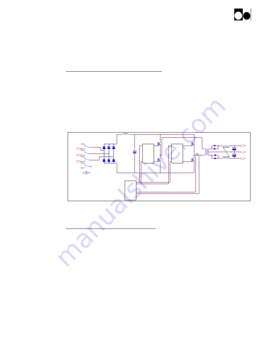
Current mode Push-Pull regulator
The Push-Pull circuit can be divided in following blocks:
- Pulse Width Modulator module.
- Gate driver for the FET's
- Power output stage with FET's .
- Power transformer
- Output Filter.
4.4.4
Pulse Width Modulator module
Schematic:
84663
Assy.
84662
The current mode control system generates the pulse width modulated signal according to the
output voltage of the converter.
The circuit is build upon U404 Current mode controller chip
From the controller chip internal oscillator signal the current mode controller chip U404 generates
two alternating pulse width controlled signals "A" and "B". The saw tooth current signal from the
current transformer controls the maximum output current.
The saw tooth signal of the U404 oscillator is mixed with the current signal from the cycle by cycle
current transformer signal is used by the U404 to switch off the FET's, when the level of the output
voltage feedback opto-coupler is reached.
This saw-tooth mixing, also called slope compensation is about 20%.
The compensation amplifier of U404 is an integrator with zero at app. 100 Hz and a pole at app. 1
kHz. Gain between 100 Hz and 1 kHz is app. 25 dB.
The current mode controller has a built in "low supply voltage" detector, which prevents
11
7
3
PHA SE3
FET Driver
A 1
A 2
GND
9
5
1
+V
-V
PHA SE1
PHA SE2
U
V
W
+
-
12
8
4
FET Driver
10
6
2
UC3846
PWM
Controller
The figure shows the Current mode Push-Pull regulator.


