System 8700 User Manual
Rev 0.95
Page 23 of 32
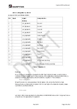
4.3.1.1.
Register 4, bit 13
Command: STATus:OPERation:REG4.
Bit
Input
Signal
(Index)
Interpretation
0
-
eIL_RegBoard0
Drive AD
1
-
eIL_RegBoard1
Drive BC
2
-
eIL_RegBoard2
Temp AD
3
-
eIL_RegBoard3
Temp BC
4
-
eIL_RegBoard4
Temp AD+BC
5
-
eIL_RegBoard5
PS Fail
6
-
eIL_RegBoard6
Overload
7
-
eIL_RegBoard7
Earth leak
8
-
eIL_RegBoard8
Over temp
9
-
eIL_RegBoard9
Current DCCT
10
-
eIL_RegBoard10
Trip in
11
-
eIL_RegBoard11
Trip out
12
eIL_RegBoard12
Pre trig fault (warning)
13
eIL_RegBoard13
Polarity signal missing (warning)
Table 7 Register 4
Example:
If e.g. we have an interlock connected to the first input module, module 1, and the wire is
connected to the modules input 5, this is what we in the table above call input bInterlock1_5,
please see Table 5, this would be the 3rd interlock in register 2. The command;
STAT:OPER:REG2?
Would then return 4, corresponding to the bit pattern 100, where the third bit is high.
Because there is a high signal in register 2 bit 11 is set high in the Operation register, please
see Table 3, and the command
STAT:OPER?
will return 2048, corresponding to the bit pattern 100000000000 where bit 11 is high as there is
at least one error signal active in register 2.


