background image

MAGNET POWER SUPPLY SYSTEM 9100 


                                                                                                                                      33


DANFYSIK A/S - DENMARK. 


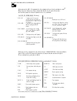
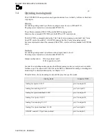
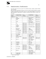
GAIN adjustment 
 
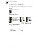
The GAIN adjustment can automatically adjust the scaling factor of the selected channel to 
only nines. That is e.g. 99999 for the 16 bit output current reading. This adjustment is only 
useful for the output current and voltage read back (CH0, CH2, CH8, CH11 and CH12) Please 
do not use this feature if the output reading is in Volts and Amps and for not applicable 
channels.  
To auto adjust to a specific value, please use the “Esc”ADSET command. 
 
To activate the automatic GAIN adjustment following steps must be preformed: 
 

-  

Select SW3 as above. “setting number14" 

-  

Select the desired channel number “lever 1 to 5" on SW4 

-  

Set lever 8 on SW4


to ON 

-  

Ensure that the AD input signal is set to 100% 

-  

Press the Setup Button 

-  

To restore the Gain value to default factory setting, please set lever 7 to one before 
pressing the Setup Button. 


Summary of Contents for SYSTEM 9100

Page 1: ...MANUAL MAGNET POWER SUPPLY SYSTEM 9100...

Page 2: ...be disclosed or transmitted to others without DANFYSIK s authorisation REV By Date Description Pages 1 0 CSN 12 04 2010 Initial All 2 0 CSN 18 06 2010 Chapter 2 5 Two or more SYSTEM 9100 in parallel...

Page 3: ...ent setting 22 3 2 7 Polarity reversal 22 3 3 OPERATING BY RS 232 RS422 OR RS 485 I O 24 3 3 1 Setting up the MPS via display board 24 3 3 2 Data communication 36 3 3 3 Termination using RS 422m or RS...

Page 4: ...r 56 4 7 2 Aux power loop CPU 56 4 7 3 Aux power FAN 57 4 7 4 Aux power primary 57 4 8 DCCT TRANSDUCER 57 4 9 BIPOLAR OUTPUT STAGE H BRIGDE 57 5 SYSTEM 9100 INTERFACE SPECIFICATION 58 AC Mains connect...

Page 5: ...research laboratory users around the world The System 9100 is the new generation of high performance Power Converters suitable for many high current and voltage applications where size and cost are es...

Page 6: ...rimary switching type that operate after the Zero voltage switch mode principle PERFORMANCE Warm up time cold 30 min Warm up time stand by 15 min Drift long term 8 hours 10ppm Line regulation 10 slow...

Page 7: ...t voltage 2 digits V Interlock status text string Push buttons and LED s OFF Button LED Reset interlock Button LED ON Button LED Menu Button Out of regulation LED Remote control interfacing RS232 as s...

Page 8: ...Operation Ambient temperature 15 40 C Storage temperature 20 70 C non condensing CABINET LAY OUT Material Steel Dimensions W x D x H 482 mm x 550 mm x 132 5 3U 19 inch rack mount Weight 32 kg shippin...

Page 9: ...FYSIK A S This warranty shall not apply to any equipment which has become defective or unworkable due to mishandling improper maintenance incorrect use radiation damage or any other circumstance not g...

Page 10: ...or electric power supplies should be respected and the following conditions and installations should be available A normal dust free room with humidity not above 80 and a room temperature within 15 to...

Page 11: ...Power Supply the following points should be checked carried out Check that the main voltage and frequency matches to the specified and labelled requirements Check that screw connections from the outpu...

Page 12: ...s to all masters at the port REMOTE Address all the masters so each unit has a unique address See chapter 3 3 1 for setup address in local and remote mode MPS no 1 addresse X MPS no 2 addresse X 1 MPS...

Page 13: ...supply ON for the first time it is recommended to activate it in the LOCAL CONTROL mode as this is the easiest way to get started If any Interlocks are set push the Reset button 8 Remove the faults if...

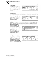
Page 14: ...nt and voltage the pull down menus are always displayed left aligned In other words it is the menu bar that rolls over the pull down region With visible menu bar activating the or arrow buttons the me...

Page 15: ...res a bit the mathematical parentheses idea but is fast to use in some cases Hint Pressing the MENU key the first displayed menu will either be the SET or the INTL menu The last one if at least one in...

Page 16: ...ower is OFF LED 5 Main power OFF push button 6 READY LED indicates when the actual output current is within a predefined limit 7 Control Power ON Back light is lit 8 Interlock RESET push button 9 Sum...

Page 17: ...SET 000000 ppm When full output current is set it displays Iset 999999 ppm which is to be read as 99 9999 of full scale If required a setting in Ampere with six digits and a decimal point can be adapt...

Page 18: ...de LOCal or REMote Remote is shown inversed Regulation status ReaDY or not Ready is shown inversed and not ready as three bars Main power ON or OFF OFF is shown inversed The controlling address in a m...

Page 19: ...an auto increment decrement operation Pop Up Window The picture to the right shows a pop up window displaying many interlocks The bar at the bottom indicates that there is no further information downw...

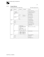
Page 20: ...AX MIN Set current to one end 0 Set current to zero 100 Set current to max CMD Control Command line REM Set to Remote Control LOC Set to Local control ADR Select a multidrop address INTL Display Inter...

Page 21: ...utput setting current Output current 5 significant digits CHN 9 17 A D Channels 9 to 18 Iout Not Used Output current for display Output voltage for display Not Used Not Used Not Used Not Used Iset val...

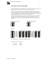
Page 22: ...ply is designed to work mainly in the first and third quadrant i e either positive output voltage and current or negative output voltage and current Working in the second or fourth quadrant is limited...

Page 23: ...MAGNET POWER SUPPLY SYSTEM 9100 23 DANFYSIK A S DENMARK...

Page 24: ...is set up The parameters are first acknowledged after pressing the SETUP switch S4 The SW3 switch position can also be seen as a binary number The following table to the right shows the SW3 number pos...

Page 25: ...T CARE DON T CHANGE SW 3 ON ON 1 2 3 4 1 2 3 4 5 6 7 8 D13 D20 D24 D30 S etup SET UP S R eset Interlock LED indications Mode 0 red LED LED 13 LED 14 LED 15 LED 16 LED 17 LED 18 LED 19 LED 20 Status OF...

Page 26: ...l immediately display the present setting on the red LEDs below SW4 SW3 FOR LOCAL LINE SW3 FOR REMOTE LINE ON ON 1 2 3 4 1 2 3 4 4 1 Parameters PARITY 7 8 Bits 8 Bits 1 2 7 Bits STOP Bits OFF OFF ON O...

Page 27: ...cation problems due to noise and high differential voltages that may jam the input signals The REMOTE line addressing can be used for controlling more power supplies through one serial line one PC Gro...

Page 28: ...D Default setting after COLD BOOT Remote Line RS485 Communication Disabled 0 RS485 Line turn around time Disabled Line turn around set bit 0 RS485 Line turn around time Disabled Line turn around set b...

Page 29: ...with or without error code will overide this setting 2 REMOTE AUTO ANSWER DISABLED 1 BELL Without further information 2 BELL Followed by error in code 3 BELL Followed by error in text ENABLED 1 2 3 3...

Page 30: ...es WA 123 equals WA 000123 For trailing zeroes WA 123 equals WA 123000 SW3 FOR AUXILIARY SETUP 1 ON 1 2 3 4 8 SW4 WA ZEROES TRALING A V LEADING INTERLOCK CLEAR CLEAR OFF CLEAR DAC 17 TRANSPARENT 0 1 1...

Page 31: ...ng the rest energy in the magnet to decay The time delay is only inserted if the power supply was ON before invoking the POL command That is when just changing the polarity in the power OFF mode no ti...

Page 32: ...g steps must be preformed Select SW3 as above setting number14 Select the desired channel number lever 1 to 5 on SW4 Set lever 8 on SW4 to OFF The LEDs will display the present Offset value Ensure tha...

Page 33: ...do not use this feature if the output reading is in Volts and Amps and for not applicable channels To auto adjust to a specific value please use the Esc ADSET command To activate the automatic GAIN ad...

Page 34: ...ffset value Set the AD channel value WA for DA 0 to a value that gives a zero output Press the Setup Button A given DA 0 0 or WA 0 will now produce a zero output at the DA channel Due to the unipolar...

Page 35: ...R SUPPLY SYSTEM 9100 35 DANFYSIK A S DENMARK pressing the Setup Button CHANNEL VALUE DA channel spec Equal to 0 Output current 16 bit WA range as default 1 Not used 2 Not used 3 Not used 4 Output volt...

Page 36: ...N 4 RX_LOC 9 TX_REM 5 RX_LOC 10 TX_REM 6 7 15V 11 RX_REM 8 9 15V 12 RX_REM 13 Vcc Vcc Rx Signals received by the Control Module from its host Tx Signals transmitted by the Control Module to its host N...

Page 37: ...The external resistor is preferable Hint This resistor can be placed inside the last DB 25 plug for the remote line and the DB9 plug for the Local line When using the RS 485 or the RS 422 line in the...

Page 38: ...nternal transmit buffer regardless of the selected baud rate All commands can be divided into three sections a Directive commands Eg the N command that turns the power supply ON b Status commands Eg t...

Page 39: ...REM Is it an error reply ERROR RE REM Mark the error code ELSEIF RE OK REM Is it a good reply BRAKE REM then exit DO loop ELSEIF J 6 REM Try only six times IF LEFT ERROR 1 CHR REM Was it error reply...

Page 40: ...ameter Read the status of the running stack S2 Please refer to the software manual about SW2 Ramp Profile Commands for full instructions The figure shows an example of one ramp profile stack Ps not al...

Page 41: ...will be used for all set values Only one stack is available This profile method is especially useable for faster and more accurate curves fitting profiles e g as a function generator To use the Equal...

Page 42: ...e Auto Slew Rate Ramp Profile Method an automatic ramp profile will be generated and executed when issuing a new current set point In other words this feature acts like a software driven slew rate con...

Page 43: ...e time between two points can be between 0 2 to 65535 seconds Maximum numbers of stacks 15 Maximum number of lines in a stack 15 The limits of the Equal time slot method ramp profile SW are The set va...

Page 44: ...ge ERRT Text string error message F Main Power OFF LALL Listen ALL LOC Change to Local Control LOCK Lock the MPS in Local Control N Main Power ON NASW No answer mode NERR No error message PO Polarity...

Page 45: ...the special options ESC BAUD Configures the Baud rate for the serial lines ESC COLDBOOT Configures the power up state Wake up position P r e f e r r e d n e w c o m m a n d DA 0 ESC CPURESET Hardware...

Page 46: ...UPPLY SYSTEM 9100 46 DANFYSIK A S DENMARK R Write data to the stack RAMP RSHTN LWB Control the stack operation P r e f e r r e d n e w c o m m a n d DA 0 RAMPSET Time Multiplicant LWN C Configure the...

Page 47: ...STEM 9100 Hardware For enabling analog mode by hardware some jumpers need to be set The jumpers are located on control module PCB 91376 Jumper configuration J502 in position 1 and 2 J503 in position 1...

Page 48: ...e 6 COM GNDD ST818 close ST806 open Earth leak status ST818 open ST806 close 7 I MON ST819 close ST807 open Overcurrent status ST819 open ST807 close 8 RTN AUX GNDA ST821 close ST809 open GND Parallel...

Page 49: ...deep This allows for quick replacement of all modules and print circuit boards in Magnet Power Supply Thus this reduces service time and total down time The System 9100 is a full bridge phase modulate...

Page 50: ...0 1A ON OFF SUM_INTL X24 OPTO STATUS CONTROL X25 16 BIT D A V set 15VDC_P 2A ON TRIG IN OUT ROM Output Current INTERLOCK ON OFF CONTROL 5V 0 1A RECTIFIER 3PHASE U V W AUX POWER PCB Over Temperature OP...

Page 51: ...ULE X414 AC INPUT FILTER RECTIFIER 3PHASE U V W OVERCURRENT BREAKER FRONT OPPERATED I 1 2 FILTER Ext Int SPI interface Select Detect 12V 0 1A PARALLEL INTERFACE X108 ON OFF SUM_INTL OPTO STATUS CONTRO...

Page 52: ...s an AFT1502 from Atmel The CPU runs at 14 7456 MHz controlled from the crystal Y202 The micro processor has built in Watchdog circuit and will reset the CPU if it for some reason stops refreshing the...

Page 53: ...or U101 converts the 15 V to 5 V for the digital circuits The buck switching regulator is an LT1765 from Linear Technology The linear regulator LM78L05 U709 regulates 15 V to 5 V for the analogue circ...

Page 54: ...ent This circuit has nothing to do with the normal ramp time controller in the regulation circuit but ensures only a proper start of the Power Amplifier The circuit is build around A509 When the main...

Page 55: ...module is to filter noisy AC signals overcurrent protecting and rectify the AC signals to DC signals 4 5 1 Overcurrent breaker An overcurrent breaker Q1 functions as power switch for the power supply...

Page 56: ...phase shift PWM controller from Unitrode 4 PWM signals A OUT B out C out and D OUT is wired to the output module where the output current is generated 4 7 Aux power supply The aux power supply module...

Page 57: ...urrent of 200 A 4 9 Bipolar output stage H Brigde The bipolar power supply can be achieved by using the standard unipolar system as the power platform added with an analogue bipolar output stage It co...

Page 58: ...ctor for 400VAC main and 230VAC control input Pin no Name I O Description Specification 1 NU 2 400 VAC 3 phase AC main input L1 3 400 VAC 3 phase AC main input L2 4 400 VAC 3 phase AC main input L3 11...

Page 59: ...ternal voltage set point Local Remote status Low LOC Open col 16 IP 10V I Analog external current set point 17 FAULT RELAY O Fault relay closed OK 18 FAULT RELAY O Fault relay closed OK 19 V MON O Out...

Page 60: ...se lines can be used for board connected detection LOCAL CONTROL X6 D SUB 9 Pole Local RS422 RS485 DB9 serial line Interface Pin no Name I O Description Specification 2 Tx Low O RS422 485 Transmitter...

Page 61: ...NC O O Open collector output up to 24V 100mA Active in minimum 2 5ms when a ramp profile has been triggered 2 SYNC O O Return line for SYNC O 3 SYNC I I Return wire for pin 4 4 SYNC I I Applying a 15...

Page 62: ...the cabinet and all heat sinks mounted on printed circuit boards to ensure a normal flow of cooling air Check that screw connections from the output terminals are tightened In dusty or dirty environm...

Page 63: ...Check connections to main contactor PHASE FAIL INTERLOCK Check all phases Check AC main power voltage MPS OVER TEMPERATURE INTERLOCK Check ambient temperature Temperature higher than 40 C Ambient tem...

Reviews: