MAGNET POWER SUPPLY SYSTEM 9100
42
DANFYSIK A/S - DENMARK.
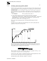
The SW will after the start command update the output current every 1.25ms. By means of
interpolation regardless of the programmed time slot value:
The ramp can be set up to run as a single shot “RAMP R”, auto iteratively (auto loop) “RAMP
RL” or HW triggered auto armed “RAMP TW”. For a full documentation on controlling the
“Equal time slot method” please refers to the software manual about Ramp Profile Commands.
If synchronization to an external event is required, it is possible to arm the ramp sequence first
with the synchronization command “RAMP T”. A hardware signal on the trigger input X9 pin
1&2 (10 to 24V) or a “RAMP R” command will start the sequence.
If more power supplies have to be synchronized, one of the supplies has to be appointed as
master. Connecting the master trig output X9 pin 3&4 to the other supplies trig input will start
the other supplies when the master is triggered. A maximum skew of 1.25ms between the
supplies may be expected. (an external 15V auxiliary supply is needed, as the trig output is an
open collector and the trig input is an optocoupler input.)
3.3.8
Auto Slew Rate Ramp Profile method.
With the”Auto Slew Rate Ramp Profile Method” an automatic ramp profile will be generated
and executed when issuing a new current set point. In other words, this feature acts like a
software driven slew rate controller.
Two shapes can be preselected. A cosines and a square shape. Which shape is selected, is
given by the Aux2 setting bit 4. 0 = Cosines & 1 = Square
Example: If the power supply is at 10% output current, the slew rate is set to 1 second
(„esc‟<slopetime 1.1) and a set command “da 0.600000" is given the power supply will
start at 10% and run to 60% within ½ a second with the selected shape.
The positive and negative slew rate value can be set individually. Please refer to the SW
manual describing the “„esc‟< slopetime „val1',‟val2'” for further information.
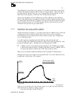
The two ramp profile shapes has both its benefit and draw backs. The cosines shape is smooth
all the way but has a higher di/dt in the middle and results in a sinus output voltage shape on an
inductive load whereas the square shape in a trapezoidal output voltage
The ramp profile consist of 80 points with HW interpolated points in-between. Each of the 80
points has a distance of 2.5 ms. In-between. Profiles with shorter distances than 200ms
(80*2.5ms) are achieved by omitting points. Eg. a ramp time of 20ms will only consist of 8
points thereby resulting in a more coarse profile.
The figures below shows the shape of the two ramp profiles.


