MAGNET POWER SUPPLY SYSTEM 9100
47
DANFYSIK A/S - DENMARK.
3.4
Operating in analog mode
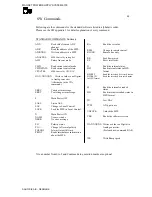
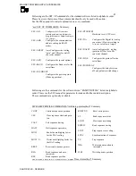
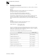
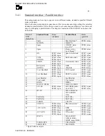
The SYSTEM 9100 can operate in analog mode and can be set either by software or hardware
via jumpers.
Software:
For enabling analog mode by software no jumpers must be set on J502 and J503.
The jumpers are located on control module PCB 91376.
The software command ANACTRL puts the MPS in analog mode.
Likewise, the command CPUCTRL sets the MPS in CPU control mode.
The ANACTRL command switches the I Set Value between analog control and I Set Value
from CPU control board DAC. ANACTRL change the I Set Value into analog control.
For more information about the command ANACTRL, refer to software manual for SYSTEM
9100.
Hardware:
For enabling analog mode by hardware some jumpers need to be set.
The jumpers are located on control module PCB 91376
Jumper configuration: J502 in position 1 and 2
J503 in position 1 and 2
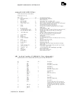
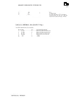
In order for controlling and monitoring the different analog modes, several pins are available
for these uses. The connector X108, back on the MPS, is dedicated for analog controlling and
monitoring. For detail pin description, see chapter 4.1.2.
The table below shows the analog modes and the pins for a specific mode.
Analog mode
Connector X108
Analog I set point: 0-10 V
pin 16 and pin 23
Analog I monitoring: 0-10 V
pin 7 and pin 25
Analog I set point read back 0-10V
pin 10 and pin 25
Analog V set point: 0-10 V
pin 15 and pin 20
Analog V monitoring: 0-10 V
pin 19 and pin 24
Analog V set point read back: 0-10 V
pin 9 and pin 24
ON/OFF control 12 V galvanic isolated
pin 14 and pin 2


