background image


FLS 3D


Industrivej 24C 

DK-3550 Slangerup 

Denmark 

Tel. +45 4737 3800   

Fax: +45 4737 3809 

info@daniamant.com 

www.daniamant.com


FLS 3D Manual Version 1  

Daniamant A/S 

17


Information in this document is subject to change without notice. No part of this document may be 
reproduced or transmitted in any form or by any means, electronic or mechanical, for any purpose, 
without the express written permission of Daniamant Electronics A/S. 
  
Copyright © 2017 by Daniamant Eletronics A/S. All rights reserved. 
  

Protected by USA Patent 5530680 and European (UK) Patent 0624253 

  
Author: Chris Phillips  
Last Updated: 06.10.2017 (Johnny Christensen) 
  
For up to date information and advice, please telephone, browse our Website, or send us an E-Mail: 
 

e-mail:  info@echopilot.com 

website: www.echopilot.com 


Summary of Contents for Echopilot FLS 3D

Page 1: ...FLS 3D Industrivej 24C DK 3550 Slangerup Denmark Tel 45 4737 3800 Fax 45 4737 3809 info daniamant com www daniamant com FLS 3D Manual Version 1 Daniamant A S 1 Manual for FLS 3D Forward Looking Sonar ...

Page 2: ...t the maximum performance pleasure and safety from your equipment so please take the time to read the instructions Please observe the following warnings Please do not cut the transducer cables they are fine multi core cable matched to the transducer Please do not remove the transducer plug from its cable if a hole is too small make the hole bigger Any join in the cable will reduce sensitivity perf...

Page 3: ...n 1 Daniamant A S 3 INDEX 1 Operating Instructions 4 2 Setup Instructions 5 3 How FLS Technology Works 6 4 Guidance on use 7 5 Installation Instructions 8 Transducer Installation 8 Transducer Interface Installation 10 Visual Processor Installation 11 Keypad Installation 13 Wiring Overview 13 6 Technical Specifications 14 7 Fault Finding 15 ...

Page 4: ...on is lost this determines the maximum view ahead though often 10 to 20 times depth ahead In the horizontal plane the 3D covers an area about 30 degrees either side of the centre line of the boat or 60 degrees overall Calibration in degrees can be seen on the display In the vertical plane the 3D can see from under the transducers to the sea surface ahead The depth colour scale on the right hand si...

Page 5: ... down keys on the Keypad Use the up key to increase the range and the down key to decrease the range If you press the up or down key several times it will jump instantly to the required range For example if you are on the 40m range and you press the up key three times the range will jump instantly to the 100m range Range settings 40m 60m 80m 100m 150m 200m 2 Setup Instructions Settings Menu In ord...

Page 6: ...ics The transmit ping radiates at all angles down and out from the vessel hits the seabed and some of it is returned to the transducer s receivers As the ping travels further away from the boat it hits the sea bed at an increasingly acute angle At a certain point the angle will be so acute that the ping is not returned and the seabed information is lost this determines the maximum view ahead When ...

Page 7: ...e transducer reducing sensitivity or sometimes obliterating all the picture so take care Manoeuvre with the minimum use of astern reverse power especially with the propeller on twin screw vessels on the side of the transducer Turbulence from other vessels especially in shallow water can also adversely affect performance Algae normally in spring Plankton and pollution can all show up as noise on th...

Page 8: ...o access for maintenance Do not fit downstream of any other through hull fittings for example intakes log toilet sea cocks etc and choose a location with good access for withdrawing the transducer for cleaning The transducer should ideally be vertical in the fore and aft plane at running trim If it leans forward the seabed will appear to slope up and if it rakes aft then a degree of surface clutte...

Page 9: ...p Denmark Tel 45 4737 3800 Fax 45 4737 3809 info daniamant com www daniamant com FLS 3D Manual Version 1 Daniamant A S 9 Sailing direction Top view Note Fit port transducer red bands to port and starboard transducer green bands to starboard ...

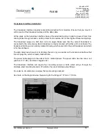
Page 10: ... transducer is connected to the correct plug Each transducer is clearly marked with either port or starboard The transducer interface is also clearly marked showing which socket is for the port transducer and which is for the starboard The data cable has a five pin mini din plug there is only one socket on the transducer interface that this will plug into which is clearly marked data The power cab...

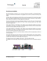
Page 11: ... negative 0v If the visual processor is connected to a 12v supply then the transducer interface must also be connected to a 12v supply The positive of both the transducer interface and the visual processor must be at the same potential with respect to ground If the visual processor is connected to a 24v supply then the transducer interface must also be connected to a 24v supply The positive of bot...

Page 12: ...ant com www daniamant com FLS 3D Manual Version 1 Daniamant A S 12 The visual processor will require four mounting screws or bolts which will go through the mounting brackets We advise the use of stainless steel fixings As shown on the diagram below the spacing for the fixings is 260 mm x 185mm ...

Page 13: ...for panel mounting It is provided with a stainless steel mounting bracket two plastic m6 studs and two m6 plastic nuts Once you have decided on the best position for the keypad making sure that the cable reaches the visual processor cut out a rectangular hole measuring 103mm x 161mm Place the keypad into the cut out with the m6 studs already screwed into the threaded holes in the back of the keypa...

Page 14: ...3D Forward Looking Image Display 3rd part dependent Bottom Mapping Range 20x water depth Display Update Rate 1 second pr update Maximum Depth Detection 100m Maximum Forward Range 200m Operating Frequenzy 200 kHz Power Requirements 12 24 V 20W Maximum Output Power 28W Angular Accuracy 1 5 degree Roll Pitch Stabilization N A Operating System Windows Update Rate 1 1 second Video Output HDMI and VGA B...

Page 15: ... within menu Check power to the transducer interface Check com cable Poor seabed picture or excessive noise Suitable range not selected try to fill screen with seabed Poor connection of transducer Battery voltage low use Test Mode to check Tx voltage Transducer mounted at an angle Turbulence at transducer location Interference from other 200KHz sounders same boat or other boats Turbulence wake fro...

Page 16: ...ble or jumpy The FLS 3D is a Real Time Sonar not a historical recording like a fish finder so some pings will come back and some will miss It updates about once a second and two successive pictures will rarely be the same This can give an uneasy picture We recommend to test out in open water with the boat moving gently through the water Please check the videos on the website for reference ...

Page 17: ...itted in any form or by any means electronic or mechanical for any purpose without the express written permission of Daniamant Electronics A S Copyright 2017 by Daniamant Eletronics A S All rights reserved Protected by USA Patent 5530680 and European UK Patent 0624253 Author Chris Phillips Last Updated 06 10 2017 Johnny Christensen For up to date information and advice please telephone browse our ...

Reviews:

Related manuals for Echopilot FLS 3D