DB-70 Automatic Wheel Balancer
40
P/N 5900261 — Rev. A1 — January 2021
e.
Turn the Balancer Off and then
back On, to reset it, if required. The
display should be flashing, and
–a-
will appear in the Inner Display
Window.
f.
On the Control Panel, press the
F
button until the
ALU 4
Indication is
lit.
g.
Input the wheel parameters. Slide the inner distance arm to touch the Inner Edge and hold it
there to automatically determine the distance from the side of the Balancer and the wheel
diameter. These parameters are entered into the Balancer’s memory. The value should appear
in the
Outer Display Window
. You may also enter the values manually using the
A
and
D
keys.
Note
: If the values appear incorrect you can turn off the power to reset the machine and start
the process over.
h.
Determine the width of the wheel using the wheel caliper and input this value using the front
panel button labelled
B
. The value should appear in the
Outer Display Window
.
When all three measurements are correct, you are done
entering measurements.
i.
Close the Tire Cover; the Wheel spins briefly.
⚠
WARNING
Stay clear and do not touch the Wheel or
the Tire while it is rotating.
j.
The Balancer will automatically rotate and test the wheel
for balance, unless the Tire Cover switch is in the off
position. If the Tire Cover switch is off, then lower the Tire
cover and manually start the test using the start button on
the control panel.
k.
The front panel display will show the unbalanced weight
correction values for both the inner and outer wheel planes. These values are rounded to the
nearest .25 oz. Press F to view the actual unbalanced weight without rounding. If either
window displays
0.0
no corrective weights are required on that plane.
l.
Check the value on the Inner Window.
•
If the value is
00
, you do not need to add weight to the Inner Plane.
•
If there is a value—
.25
, for example—you need to add that amount of Weight to the Inner
Plane.
m.
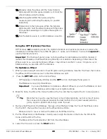
To add Weight, turn the Wheel, watching the indicators to the
right
of the
Inner Display
Window
. The Indicators light up or go out as you move the Wheel.
n.
When all of the Indicators are lit, press the Brake Pedal to hold the Wheel at that position.
o.
Clamp the Weights at Top Dead Center on the Wheel (12 o’clock high) on the Inner Edge. If
you are adding Adhesive Weight with multiple sections, center them on Top Dead Center.
p.
Check the value on the Outer Display Window:
•
If the value is
0.0
, you do not need to add Weight to the Outer Plane.
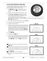
ALU 4 Weight Locations
Summary of Contents for DB-70
Page 52: ...DB 70 Automatic Wheel Balancer 52 P N 5900261 Rev A1 January 2021 Labels A...
Page 53: ...DB 70 Automatic Wheel Balancer 53 P N 5900261 Rev A1 January 2021 B C E...
Page 61: ...DB 70 Automatic Wheel Balancer 61 P N 5900261 Rev A1 January 2021 Inner Distance Arm Assy...
Page 65: ...DB 70 Automatic Wheel Balancer 65 P N 5900261 Rev A1 January 2021 Wiring...
Page 66: ...DB 70 Automatic Wheel Balancer 66 P N 5900261 Rev A1 January 2021 Maintenance Log...
Page 67: ...DB 70 Dynamic Wheel Balancing Machine 67 P N 5900261 Rev A1 January 2021 Maintenance Log...
Page 68: ...1645 Lemonwood Drive Santa Paula CA 93060 USA 2021 BendPak Inc All rights reserved Dannmar com...


