
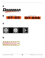
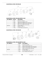
DT-50 and DT-50A Tire Changer
61
P/N 5900260 — Rev. A1 — Dec. 2020
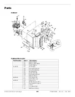
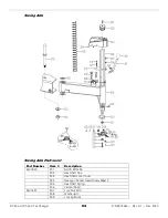
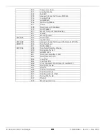
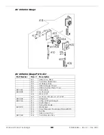
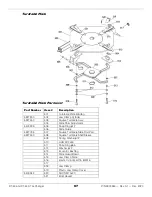
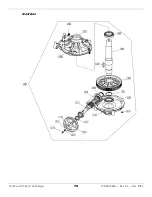
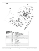
Parts
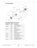
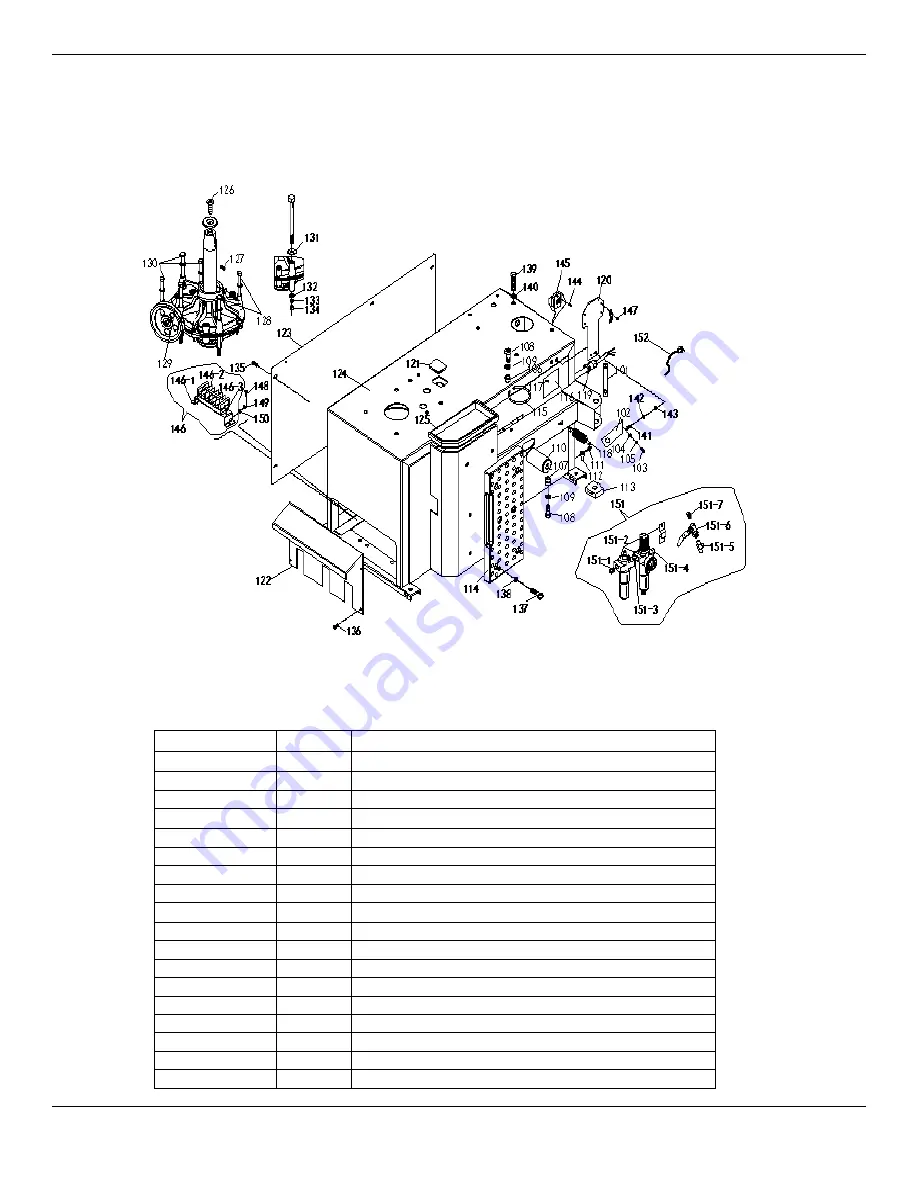
Cabinet
Cabinet Parts List
Part Number
Item # Description
101
BB Arm Shaft
102
BB Arm Shaft Baffle
103
SHCS M6x16
5400913
104
Washer
φ
6
105
Spring Washer
φ
6
106
Eccentric Bushing;
107
Metal Bushing
108
SHCS M12x35
109
Spring Washer
φ
12
110
BB Arm Shock
5327530
111
STS M5.5 X 25
112
Earth Wire Logo
5327307
113
Plastic Foot
114
Wheel Support Pad
115
Soap Bucket Support
116
Label
117
Cup Head Rivet
118
BB Return Spring
Summary of Contents for DT-50
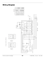
Page 57: ...DT 50 and DT 50A Tire Changer 57 P N 5900260 Rev A1 Dec 2020 Wiring Diagram...
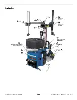
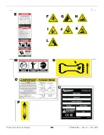
Page 58: ...DT 50 and DT 50A Tire Changer 58 P N 5900260 Rev A1 Dec 2020 Labels...
Page 60: ...DT 50 and DT 50A Tire Changer 60 P N 5900260 Rev A1 Dec 2020...
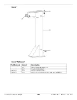
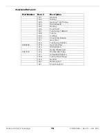
Page 73: ...DT 50 and DT 50A Tire Changer 73 P N 5900260 Rev A1 Dec 2020 Gearbox...
Page 83: ...DT 50 and DT 50A Tire Changer 83 P N 5900260 Rev A1 Dec 2020 Maintenance Log...
Page 84: ...1645 Lemonwood Drive Santa Paula CA 93060 USA 2020 Dannmar Inc All rights reserved Dannmar com...


