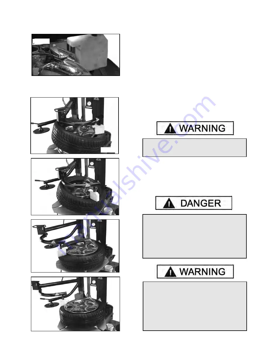
8. With the left side helper, press down on the tire near the
right side assist roller to hold the tire in the drop center.
( See Fig. 1)
9. Depress the table top pedal and rotate the tire until the
bead is mounted. The left side helper shoe will follow the tire
during rotation. ( See Fig. 2-5)
MOUNTING TUBE TYPE TIRES
1. Lubricate the beads and rim liberally.
2. Position the demount head and bead lifting tool as
described earlier. Mount the bottom bead first.
3. Round out the tube with a small amount of air. Avoid
pinching or forcing the tube. Apply rubber lubricant to the
tube.
4. Insert the tube into the tire paying careful attention not to
pinch the tube.
5. Depress the table top pedal and rotate only a short
distance at a time. This allows you to stop the process
should you suspect the tube is getting pinched.
6. Mount the top bead.
INFLATION INSTRUCTIONS
Tire inflation is performed in four steps: Restraint, Bead
Seal, Bead Seat, and Inflation. Read the explanation of
each step and understand them thoroughly before
proceeding.
Do not force the tire onto the rim. Bead damage
could result making the tire unsafe and/or
creating the risk of injury.
Fig. 1
Fig. 2
Fig. 3
Fig. 4
Fig. 5
Check inflation gauge for proper operation .
Accurate pressure readings are important to safe
tire inflation. Refer to the Operating Maintenance
section of this manual for instructions. If the rim
has been clamped from the outside for tire
mounting, release the clamps once bead seal is
obtained, lift the tire, and move the clamps to the
center of the table top.
Tire failure under pressure is hazardous. This tire
changer is not intended to be a safety device to
contain exploding tires, tubes, wheels, or bead
sealing equipment. Inspect tire and wheel carefully
for match, wear, or defects before mounting.
Always use approved tire bead lubricant during
mounting and inflation. The inflation pedal, located
at the center of the left side of the machine,
controls the flow of air through the inflation hose.
17
Summary of Contents for T-100
Page 1: ......
Page 2: ......
Page 5: ......
Page 6: ......
Page 8: ......
Page 9: ...Note Air Fitting Not Included...
Page 10: ......
Page 14: ......
Page 24: ...24...
Page 25: ......
Page 30: ...14 Insert cone attachment into fitting 15 Secure with pin 16 See final unit assembled...
Page 31: ......
Page 56: ......


