background image

REVISION A-07

CT-D-1300000

 4

40

39

17

7

37

46

49

3

38

29

19

22

31

47

48

50

34

35

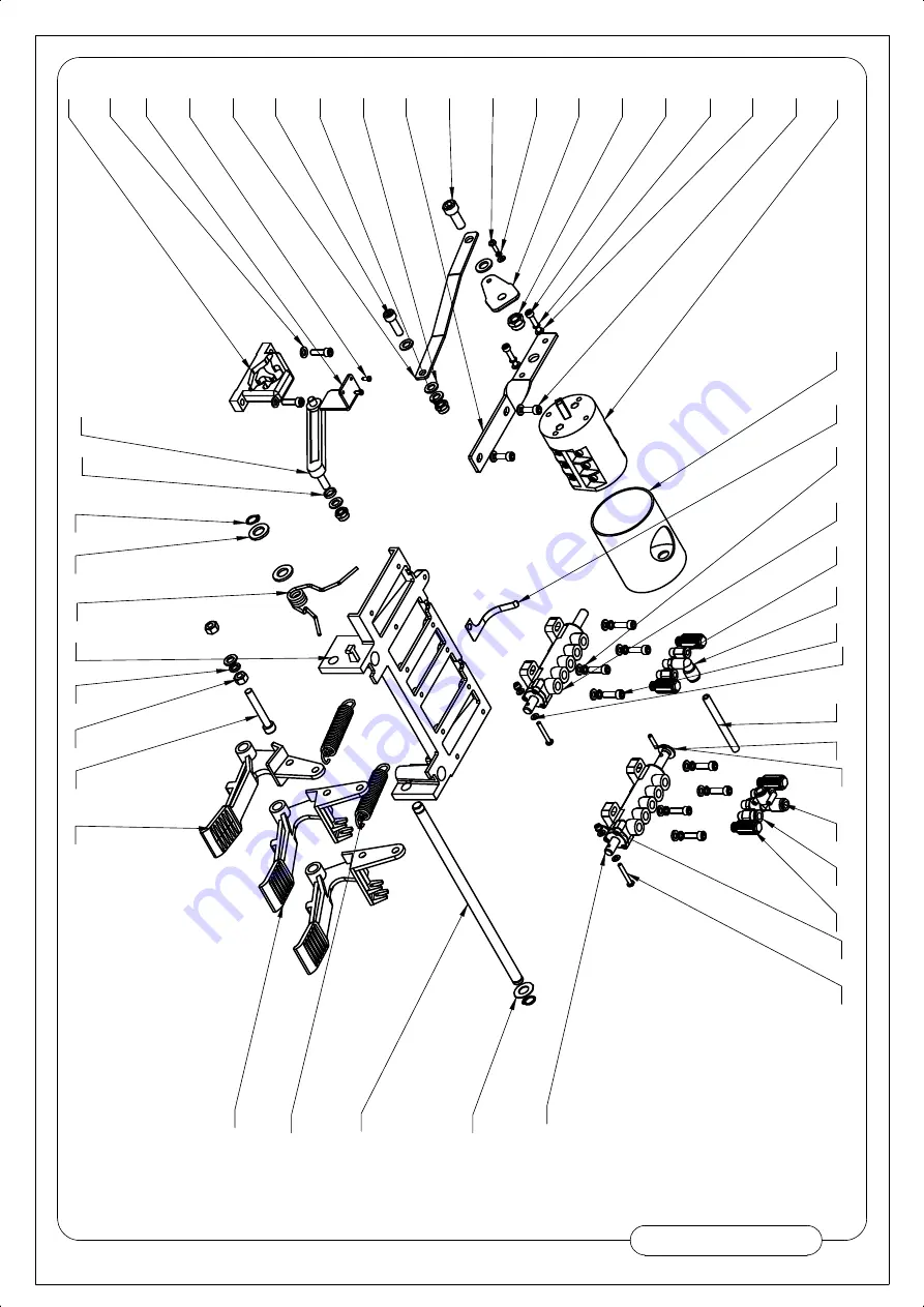
2

16

4

10

6

5

26

28

27

1

14

25

30

15

11

12

36

18

43

9

24

33

23

8

21

45

44

13

32

42

41

20

Summary of Contents for T-100

Page 1: ......

Page 2: ......

Page 3: ...O p t i o n a l A s s i s t T o w e r I n s t a l l a t i o n 2 6 3 0 P a r t s D i a g r a ms 3 0 5 1 G e n e r a l D i s c l a i me r 5 2 5 5...

Page 4: ...nstallation instructions Make sure installation conforms to all applicable Local State and Federal Codes Rules and Regulations such as State and Federal OSHA Regulations and Electrical Codes Carefully...

Page 5: ......

Page 6: ......

Page 7: ...Mo d e l H e i g h t L e n g t h Wi d t h S h i p p i n gWe i g h t T 1 0 0 8 0 5 2 0 4 0 mm 4 4 7 5 1 1 3 5 mm 3 4 2 5 8 7 0 mm 4 9 1l b s 2 2 3 k g...

Page 8: ......

Page 9: ...Note Air Fitting Not Included...

Page 10: ......

Page 11: ...on the tire sidewall 5 Pull the bead breaker shoe away from the machine and roll the wheel into position The valve stem should be in the 2 o clock position 6 Position the bead breaker shoe against th...

Page 12: ...t the mount demount head is directly over the edge of the rim Push down on the vertical slide until the mount demount head comes in con tact with the edge of the rim See Fig 5 14 Push the vertical sli...

Page 13: ...o lift the tire bead up and over the right side knob portion of the demount head Hold the tool bar in this position See Fig 9 10 NOTE This clearance will be maintained as long as the slide lock remain...

Page 14: ......

Page 15: ...al and rotate only a short distance at a time This allows you to stop the process should you suspect the tube is getting pinched 3 After upper bead is demounted remove tube and demount lower bead MOUN...

Page 16: ...Manually force the tire down into the drop center of the wheel directly across from the mount head to reduce the tensional force on the bead Depress the table top pedal and rotate the wheel to mount t...

Page 17: ...ur steps Restraint Bead Seal Bead Seat and Inflation Read the explanation of each step and understand them thoroughly before proceeding Do not force the tire onto the rim Bead damage could result maki...

Page 18: ...d position With the inflation hose attached to the tire valve and the pedal in this position line pressure is allowed to flow through the valve and to the Jet Blast nozzles on the table top for bead s...

Page 19: ...l to position two and hold about one second to begin air flow through tire valve then depress pedal to position three and hold briefly less than 1 full second The blast of air from the jets will expan...

Page 20: ...ig 1 KEEP HANDS AND FINGERS CLEAR Keep entire body away from the tire 2 Release air pressure from the tire by pressing the manual release valve button NOTE The inflation hose must be attached to the v...

Page 21: ...ty stick type pressure gauge If necessary adjust the dial of the machine gauge If the gauge is defective replace it immediately Make sure all fasteners are securely tightened and all guards and covers...

Page 22: ...ed or missing safety decal s They are available from the factory Mount Demount Tool Head Adjustment To adjust tool head lift adjust locking nut up or down until lift clearance is 1 8 to 3 16 Recheck c...

Page 23: ...ecure cover in the locked position 6 Repeat steps 1 6 Re adjust if necessary 7 After pressure limit has been set check the manual release valve function by pressing the button and releasing pressure f...

Page 24: ...24...

Page 25: ......

Page 26: ...ower Assist Tower 1 See mount location at the top of the unit 2 Align assist arm fitting holes to mount location Make sure large bolt is facing the front of the unit 3 Attach tightening ring to assist...

Page 27: ...4 Align assist arm hole to fitting 5 Place assist arm on the top of the unit Make sure arm tab goes into tightening ring fitting 6 Secure and fasten the bolt to keep the assist arm on the unit...

Page 28: ...air hose 8 Replace with new dual split hose in box 9 Reroute old hose into the new attachment As well as routing new air hose into new attachment 10 Route the new air hose through the bracket on the a...

Page 29: ...11 See power assist tower attachment with rollers 12 Fit through tower rod and pull upwards 13 Secure tightly with provided fitting...

Page 30: ...14 Insert cone attachment into fitting 15 Secure with pin 16 See final unit assembled...

Page 31: ......

Page 32: ...45 44 43 42 41 72 40 64 38 37 39 36 33 34 35 71 32 29 31 28 27 30 26 24 25 23 22 73 62 21 20 67 65 63 66 69 19 68 77 18 56 17 60 61 58 57 59 16 12 14 15 13 11 10 9 8 7 74 6 55 5 3 4 75 54 2 1 70 78 R...

Page 33: ...W 14 19 C 01 1000002 PROTECTIVE COVER 1 20 C 54 1000006 RUBBER PAD PLATE 1 21 GB T 70 1 2000 M8 20 INNER HEXA CYLINDRICAL SCREW 3 22 C 54 1000005 RUBBER FOOT 4 23 CT C 2100000 BEAD BREAKER BLADE 1 24...

Page 34: ...0012 SCREWS M14X42 2 57 GB5781 M8 20 HEXANGULAR BOLT 4 58 CT K 1100000 QUICK INFLATION PEDAL ASSY 1 59 GB95 8 FLAT WASHER 6 60 GB41 M8 HEXANGULAR NUT 2 61 C 90 1000001 STOP UP 1 62 GB93 8 STANDARD SPR...

Page 35: ...11 10 1 2 24 21 20 14 16 15 19 12 18 13 4 26 25 23 22 3 5 6 7 27 8 9 17 REVISION A 05 C 5B 1300000...

Page 36: ...HEXA CYLINDRICAL SCREW 1 12 C 31 1300013 DEMOUNTING HEAD 1 13 C 54 1300007 SHOCK ABSORBER WASHER 1 14 C 54 1300008 PRESS WASHER 1 15 GB93 10 STANDARD SPRING WASHER 1 16 GB5781 M10 25 HEXANGULAR BOLT...

Page 37: ...00001 AIR GUIDE ROTATION BUSHING 1 3 FPC 10 02 MALE STRAIGHT 4 4 FPC 8 01 MALE STRAIGHT 4 5 GB3452 1 100 2 65 G HYDRAULIC PNEUMATIC RUBBER O RING G TYPE 1 6 GB3452 1 60 2 65 G HYDRAULIC PNEUMATIC RUBB...

Page 38: ...PACER 1 8 FPL 8 02 INSERT ELBOW 8 R1 4 1 9 FPL 8 01 INSERT ELBOW 8 R1 8 1 10 GB893 2 30 ELASTIC RETAINING RING B TYPE 1 11 GB70 1 M6 20 INNER HEXA CYLINDRICAL SCREW 12 12 GB95 6 FLAT WASHER 12 13 GB61...

Page 39: ...K 3100002 CONNECT NUT 1 5 FPL 8 01 INSERT ELBOW 8 R1 8 1 6 GB6170 M4 HEXANGULAR NUT 1 TYPE 3 7 CT K 3110000 EXHAUST VALVE ASSEMBLY 1 8 CT K 3100001 PRESSURE GAUGE COVER 1 9 FPC 8 02 MALE STRAIGHT 1 1...

Page 40: ...FLATE VALVE 1 2 CT K 2200001 COVER OF QUICK DEFLATE VALVE 1 3 CT K 2210000 FILM CHIP 1 4 CT K 2200003 PRESS WASHER 1 5 GB41 M6 HEXANGULAR NUT 4 6 GB70 1 M6 40 INNER HEXA CYLINDRICAL SCREW 4 7 FPL 8 02...

Page 41: ...10 19 13 29 27 17 12 2 18 26 25 24 1 3 23 11 15 5 4 14 6 9 28 7 8 22 21 16 20 REVISION A 01 CT K 1100000...

Page 42: ...15A SCREWS PLUG R1 8 x10 2 16 GB95 10 FLAT WASHER 2 17 GB889 1 M8 1 TYPE PREVAILING TORQUE TYPE HEXAGON LOCK NUT 1 18 GB889 1 M6 1 TYPE PREVAILING TORQUE TYPE HEXAGON LOCK NUT 6 19 GB894 1 14 SHAFT EL...

Page 43: ...8 56 COMMON FLAT KEY 1 8 CT J 0000003 WORM 1 9 GB894 1 50 SHAFT ELATIC BIG RETAINING RING A TYPE 1 10 GB276 6208 DEEP GROOVE BALL BEARINGS 1 11 CT J 0000005 GEARBOX TOP 1 12 GB41 M8 HEXANGULAR NUT 5...

Page 44: ...01 100000D AIR SUPPLY CONNECTOR 1 5 GB3452 1 8 2 65 A HYDRAULIC PNEUMATIC RUBBER O RING A TYPE 1 6 CT F 2000003 PRESSURE GAUGE 1 7 FPLF8 02 INSERT ELBOW 8 R1 4 1 8 PEH 02 02 FAMALE UNION TEE 1 9 CT F...

Page 45: ...OTOR 1 1KW110V60Hz 1 4 GB41 M5 HEXANGULAR NUT 1 5 GB71 M5 16 SLOTTED CONIC HEAD SET SCREW 1 6 CT DJ 0000003 MOTOR BELT PULLEY 1 7 GB1096 6 6 28 COMMON FLAT KEY 1 8 CT DJ 0000002 RUBBER WASHER 8 9 CT D...

Page 46: ...0001 SLIDE STOPPER 4 10 CT Y 5300001 GUARD BOARD 4 11 GB894 1 65 SHAFT ELATIC BIG RETAINING RING A TYPE 1 12 GB95 12 FLAT WASHER 12 13 GB93 12 STANDARD SPRING WASHER 8 14 GB5781 M12 35 HEXANGULAR BOLT...

Page 47: ...6 JH1 2020 BEARING SLIDE 1 7 GB889 1 M8 1 TYPE PREVAILING TORQUE TYPE HEXAGON LOCK NUT 4 8 GB893 1 30 ELASTIC RETAINING RING A TYPE 1 9 GB95 12 FLAT WASHER 1 10 GB889 1 M12 1 TYPE PREVAILING TORQUE TY...

Page 48: ...REVISION A 07 CT D 1300000 4 40 39 17 7 37 46 49 3 38 29 19 22 31 47 48 50 34 35 2 16 4 10 6 5 26 28 27 1 14 25 30 15 11 12 36 18 43 9 24 33 23 8 21 45 44 13 32 42 41 20...

Page 49: ...DRICAL SCREW 1 27 GB93 8 STANDARD SPRING WASHER 1 28 GB41 M8 HEXANGULAR NUT 2 29 GB95 4 FLAT WASHER 5 30 GB894 1 12 SHAFT ELATIC BIG RETAINING RING A TYPE 2 31 GB879 1 4 20 ELASTIC CYLINDRICAL PIN HEA...

Page 50: ...T Y 1 CT D 1110001 VALVE BODY 1 2 CT D 1110003 O RING 6 3 CT D 1110004 SPACER 5 4 CT D 1110002 VALVE STEM 1 5 CT D 1110005 VALVE CAP 1 6 GB845 ST2 9 13 H C CROSS PANHEAD TAPPING SCREW 3 3 2 4 5 1 6 RE...

Page 51: ...T Y 1 CT D 1110001 VALVE BODY 1 2 CT D 1110003 O RING 6 3 CT D 1110004 SPACER 5 4 CT D 1110005 VALVE CAP 1 5 CT D 1120001 VALVE STEM 1 6 GB845 ST2 9 13 H C CROSS PANHEAD TAPPING SCREW 3 REVISION A 03...

Page 52: ...to notify the Buyer or public that changes were made 6 DANNMAR products are provided and sold as is without any express or implied warranties including warranties of merchantability or fitness for pa...

Page 53: ...rranty in addition to those made in the Agreement The buyer is warned therefore to check all Warranties and review in full detail the Terms and Conditions of Sale carefully to see that it correctly re...

Page 54: ...urchaser under this warranty a Provide dated proof of purchase and maintenance records b In some cases components may be required to be shipped to the nearest DANNMAR Authorized Service center Freight...

Page 55: ...ay labor shipping or installation costs 7 Responsibilities of Purchaser under this warranty a Provide dated proof of purchase and maintenance records b In some cases components may be required to be s...

Page 56: ......

Reviews: