background image

ENGLISH

8

10

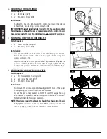
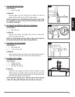
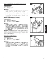
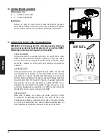
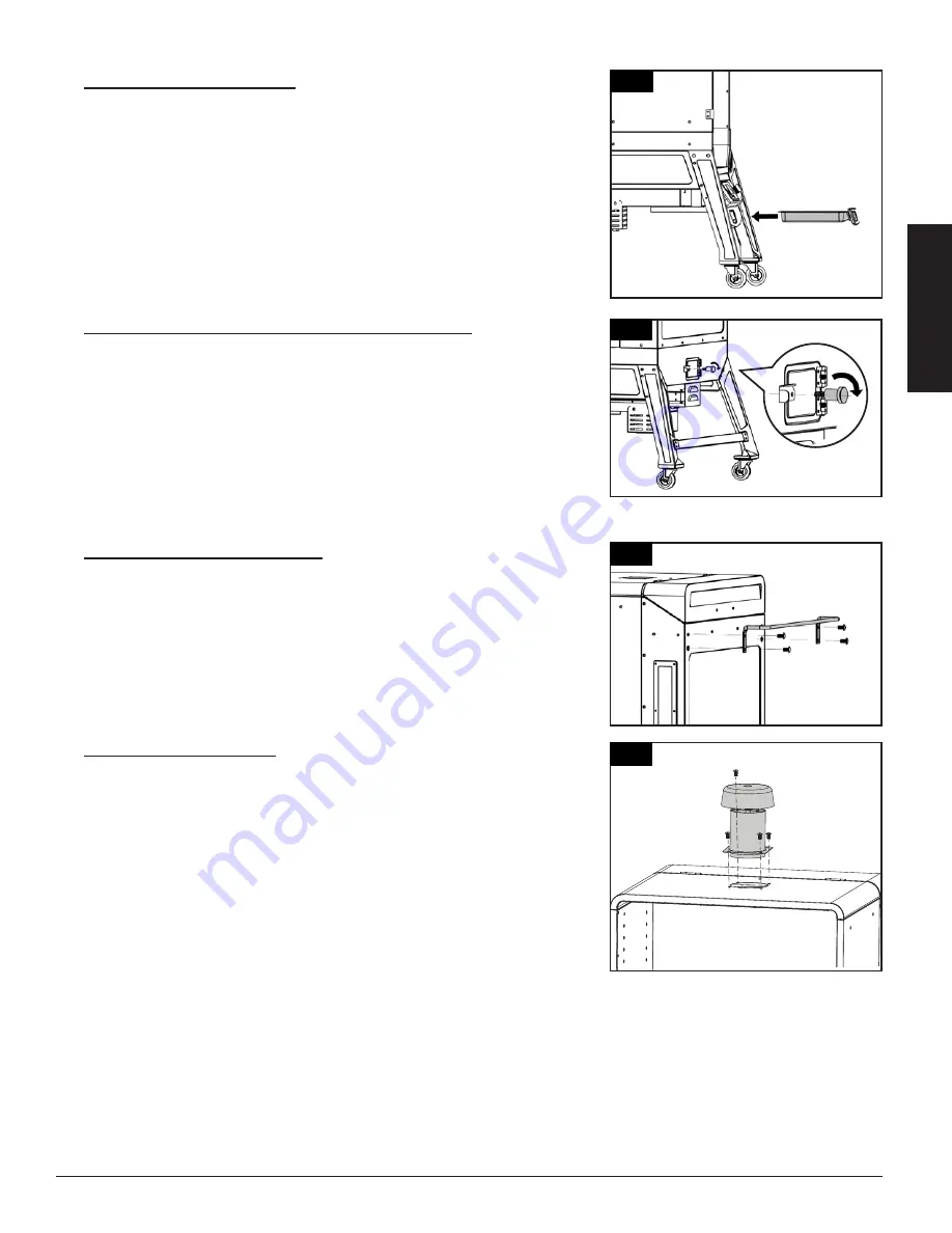
9.  PLACING THE GREASE TRAY


Parts Required:

1  x    Grease Tray 

(#16)

 Installation:

•  Slide the grease tray into the grease tray brackets on the front 

underside of the main cabinet, under the control board.

NOTE: The grease tray is completely inserted once the front of the 

tray is pushed in as far as it can go, with no gap between the grease 

tray and the front panel.

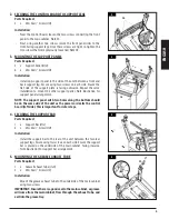
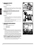
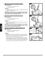
10. ATTACHING THE HOPPER CLEAN-OUT DOOR KNOB


Parts Required:

1  x    Door Knob 

(#A)

 Installation:

•  Attach the door knob to the hopper clean-out door by rotating the 

part into the hole on the door. 

NOTE: To use the hopper clean-out feature, simply loosen the door 

knob, raise the clean-out door latch and open the door. 

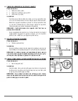
11.  MOUNTING THE BACK HANDLE


Parts Required:

1  x    Back Handle 

(#5) 

4  x    ¼–20x⅝" Screw 

(#C)

 Installation:

•  Mount the back handle onto the back side of the hopper using four 

screws. Note correct position in illustration with handle on top.

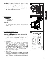
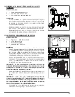
12.  SECURING THE CHIMNEY


Parts Required:

1  x  Chimney Cap 

(#3)

1  x  Chimney Stack 

(#4)

4 x #10–24x½" Screw (

#D)

 Installation:

•  Locate the chimney opening on the top of the main cabinet. From the 

outside, secure the chimney to the top panel using four screws. The 

screw will fasten to the self-clinching nut on the inside of the cabinet. 

Next, twist the chimney cap onto the top.

NOTE:  Adjust the chimney cap to affect the airflow inside the main 

smoker. If cooking at low temperature, keep the cap more open.

11

12

9

16

A

5

3

4

Summary of Contents for PIT BOSS SPORTSMAN PB5000SP

Page 1: ...ire manual before installation and use of this electric pellet fuel burning appliance Failure to follow these instructions could result in property damage bodily injury or even death Contact local bui...

Page 2: ...Back Handle 8 Securing The Chimney 8 Installing The Lid Stopper 9 Mounting The Cabinet Door Handle Door Latch 9 Installing The Cooking Components 9 Using The Hooks 10 Connecting To A Power Source 10 C...

Page 3: ...Latch x1 12 Power Cord Bracket x1 13 Support Bar x1 14 Water Pan x1 15 Flame Tamer x1 16 Grease Tray x1 17 Grease Tray Brackets x2 18 Support Panel x2 19 Wire Components Housing x1 20 Grease Exhaust T...

Page 4: ...ur support legs must be arranged correctly to be able to properly install the support panels and support bar in a later assembly step Mount one support leg to the smoke cabinet using three screws Repe...

Page 5: ...ote illustration for support panel arrangement NOTE The support panel with two holes along the bottom should be on the same side of the unit as the power cord exits the control board left side This is...

Page 6: ...in 7A Next loosen the nut on the pre mounted clip bracket and guide the power cord through the clip bracket Once through tighten the nut and wrap the power cord on the bracket until unit is in use Not...

Page 7: ...ply loosen the door knob raise the clean out door latch and open the door 11 MOUNTING THE BACK HANDLE Parts Required 1 x Back Handle 5 4 x 20x Screw C Installation Mount the back handle onto the back...

Page 8: ...C 15 INSTALLING THE COOKING COMPONENTS Parts Required 12 x Cooking Grid Support Brackets 2 5 x Cooking Grids 1 1 x Water Pan 14 1 x Flame Tamer 15 Installation Insert six cooking grid support brackets...

Page 9: ...it trips it increases in sensitivity If the GFCI keeps tripping replace the outlet or change to a non GFCI outlet ON THE ROAD Disconnect the igniter from the main wiring harness Use the manual start...

Page 10: ...la poign e arri re 17 S curisation de la chemin e 17 Montage du bouchon du couvercle 17 Fixation de la poign e et du loquet de la porte d armoire 18 Installation des composants de cuisson 18 Utilisat...

Page 11: ...upport de cordon d alimentation x1 13 Barre d appui x1 14 R servoir d eau x1 15 R ducteur de flamme x1 16 Plateau graisse x1 17 Supports du plateau graisse x2 18 Panneaux de support x2 19 Bo tier des...

Page 12: ...squ ce que toutes les vis de cette tape aient t install es 1 MONTAGE DES PIEDS DE SUPPORT SUR L ARMOIRE PRINCIPALE Pi ces n cessaires 1 x Armoire principale 7 1 x Pied de support avant gauche 23 1 x P...

Page 13: ...en utilisant deux vis de chaque c t Assurez vous que le c t plat du panneau de support est orient vers l ext rieur R p tez le m me processus pour assembler les autres panneaux de support Regardez l i...

Page 14: ...ipale l aide de deux vis IMPORTANT Assurez vous que l armoire principale est bien tanche car de la graisse sortira de l armoire principale traversera le tube d vacuation et sortira dans le plateau gra...

Page 15: ...eillez ce que l appareil soit de niveau 9 PLACER LE PLATEAU GRAISSE Pi ces n cessaires 1 x Plateau graisse 16 Installation Glissez le plateau graisse dans les supports du plateau graisse sur la face i...

Page 16: ...vis La vis se fixera sur l crou sertir l int rieur de l armoire Ensuite fixez le capuchon de la chemin e sur la partie sup rieure de la sortie de la chemin e REMARQUE Ajustez le capuchon de la chemin...

Page 17: ...bas pour qu ils soient fix s dans la bonne position R p tez le m me processus en faisant correspondre les hauteurs pour la paroi du c t droit Voir illustration 15A Placez le r ducteur de flamme sur le...

Page 18: ...l allumeur n cessite entre 200 et 700 watts de tension ce qui peut repr senter trop de puissance pour une prise DDFT La qualit du DDFT n a pas d importance mais plut t la sensibilit Chaque fois qu il...

Page 19: ......

Page 20: ...fornie comme causant des anomalies cong nitales ou autres effets nocifs sur la reproduction Pour acc der d autres informations rendez vous WWW P65WARNINGS CA GOV MADE IN CHINA FABRIQU EN CHINE IMPORTA...

Reviews: