05774-0598 <90-00122>
P
AGE
11
OPERATION
R
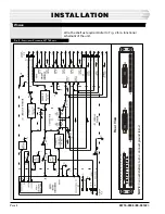
efer to Fig 2. In the idle condition, relays KA, KB and KC
are released and timers TA, TB and TC are not active. The
relays and the timers are located in slot J2. Relay KB, being
released, cut and terminate the input to the VF bridge (J3) and
it will also cut and terminate the PBX output pair. (B-5 and B-
6). This will prevent the placing of any VF coming from the PBX
on the ORDER WIRE side of the system. The PBX is connected
to port 4 of the bridge. The port 4 TX output of the bridge will go
to the input of the 44020/49018 DTMF decoder and to the input
of the PBX. (B-3 and B-4)
S
EIZURE
OF
THE
I
NTERFACE
.
Seizure from the Order Wire
The 44020/49018 decoder will reset itself every 3 seconds, after
each digit is detected.
Assume the decoder is set for address 1, 2, 3, “*” for the VNET
access code. When the user dials the 3 digit code 1, 2 , 3 the
output of the decoder detecting the correct code will operate
relay KA for 3 seconds. When the user dials the “*” after 1, 2, 3
has been detected and relay KA has operated, a ground from the
detected “*” will appear on pin 12 of the 49018 assembly.
This ground will create a latch on the 49018 that will place a
ground on pin 7 of the 49018. This latched ground is placed on
relay KB and timer TA. Timer TA is used to seize the PBX and it
can be strapped to have battery or ground as an output depend-
ing on the user’s requirement. Relay KB will operate and re-
move the shunt on the input pair from the PBX and dial tone
will be heard by the order wire user when the PBX is seized.
The PBX seizing, will place battery or ground on its M lead
which will go to timer TB. TB can be strapped for either battery
or ground as an input. TB turning on will place an additional
holding ground on timer TA and relay KB. This ground will also
operate timer TC which is a 1/2 second 1 shot timer . When TC
turns on, it will reset the 49018 latch. The ground that was
coming out of the 49018 latch, on pin. 7, will be removed. The
holding path for KB and TA is order wire timer TB which is
being held by the E lead being active. (M lead of the PBX turned
on)
The diode between TA and TB assures that the TC timer can
only be activated by timer TB turning on. The interface is now
under control of the M lead from the PBX. TC cannot retrigger
until after the ground on its input has been removed and is
reapplied.
Seizure from the PBX
When the PBX number for the interface is dialed, the M lead
from the PBX will place a battery or ground on TB of the inter-
face depending on the user’s requirement. TB will be optioned so
N
OTE
:
The 05774 Interface M Lead
(pin 34) connects to the PBX
E Lead.
The 05774 Interface E Lead
(pin 9) connects to the PBX
M Lead.


