background image

P

AGE

 4

05774-0598 <90-00122>

W

IRING

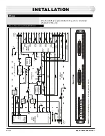
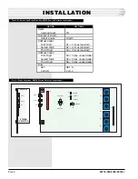
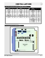
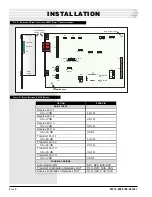
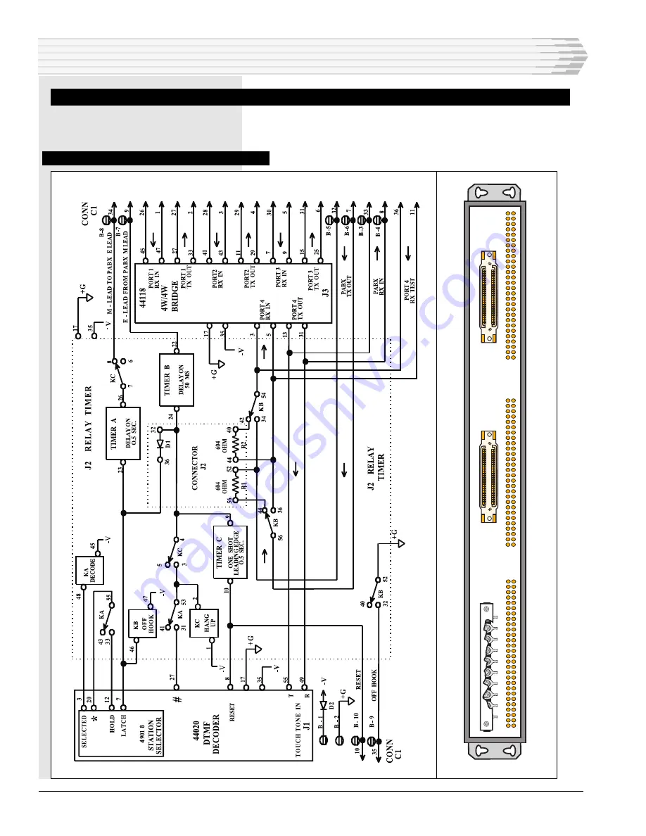
Wire the shelf as required. Refer to Fig. 2 for a functional
schematic of the unit.

F

IG

. 2 - F

UNCTIONAL

 S

CHEMATIC

, 05774 S

HELF

INSTALLATION

NOTE

: Connect -Battery to B-1. Connect ground to B-2.

1 2 3 4 5 6 7 8 9 1

0

B

C1

J1

J2

J3

C2

Rear V

iew

Summary of Contents for A18-05774 Series

Page 1: ...Dantel Inc ISO 9001 Registered Printed in the U S A INSTALLATION OPERATION MANUAL 05774 0598 90 00122 A18 05774 XX VNET ORDER WIRE INTERFACE SHELF About this Practice This practice has been reissued...

Page 2: ...e order wire side of the system will dial 3 digits plus to gain access to the order wire The same 3 digits plus will release the system Either party hanging up will release the system The unit will op...

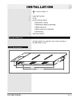
Page 3: ...ap settings 44020 DTMF Decoder 49018 Station Selector subassembly 44931 Relay Timer 49031 Relay Timer subassembly 44118 Bridge 4 Alignment procedure EQUIPMENT MOUNTING Install the shelf in an equipmen...

Page 4: ...Wire the shelf as required Refer to Fig 2 for a functional schematic of the unit FIG 2 FUNCTIONAL SCHEMATIC 05774 SHELF INSTALLATION NOTE Connect Battery to B 1 Connect ground to B 2 1 2 3 4 5 6 7 8...

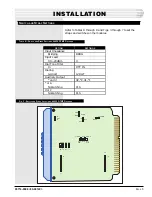
Page 5: ...TMF DECODER OPTION Input Impedance Bridging Input Level 0 to 20 dBm Dial Tone Filter In Dialing 12 digit Auxiliary Output and or A Nonlatching or C Nonlatching SETTINGS BRDG 0 DTF IN 12 DGT 2 2 1 1 PL...

Page 6: ...Digit Second Digit Third Digit Busy SET CLEAR SETTINGS IN Digit 3 S1 1 or as required S2 2 or as required S3 3 or as required S4 0 any unused code S5 0 any unused code S6 0 any unused code SET A CLR...

Page 7: ...TI TC NI IB C1 GO 1111 1111 48V TIMER C SUBASSEMBLY RO NO RTI RTO TC IC NI RI IG IB C1 C2 C3 GO BO S1 DIP Switches S2 Relay DC HI AC DC LO C8 IN OUT K1 2 IN OUT K1 5 IN OUT NO RTO IC RI IG C1 GO 0111...

Page 8: ...Transmit Port 4 0 to 7 dB FOUR WAY BRIDGE Summing Bus IN Transmit Distribution Networks OUT Receive Distribution Networks OUT STRAP IN 1R LO 2R LO 3R LO 4R HI 1X LO 2X LO 3X LO 4X HI B1X B2X B3X B4X D...

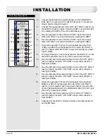
Page 9: ...termina tion 1 Verify that the straps are set per Table D Remove power from the shelf Insert 44118 module into slot 3 Reapply power 2 Connect a 600 ohm terminated dB meter across the 600 ohm out put f...

Page 10: ...ntrols 9 Move the 600 ohm terminated dB meter to the LINE XMT PORT 1 jack J2 Adjust the LINE XMT PORT 1 level control R16 for a reading of 16dBm 10 Move the 600 ohm terminated dB meter to the LINE XMT...

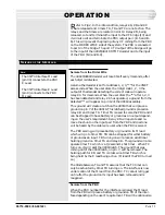
Page 11: ...B and timer TA Timer TA is used to seize the PBX and it can be strapped to have battery or ground as an output depend ing on the user s requirement Relay KB will operate and re move the shunt on the i...

Page 12: ...to the PBX E lead The PBX will have its E lead removed and relay KC will not be able to release until the PBX removes its M lead to the E lead of the VNET interface which will restore TB When the PBX...

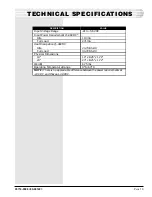
Page 13: ...ull Load Heat Dissipation 48VDC Idle Full Load Physical Dimensions 19 23 Weight Operating Temperature Range VALUE 21 to 56 VDC 110 mA 271 mA 24 73 Btu Hr 44 72 Btu Hr 19 x 8 25 x 1 72 23 x 8 25 x 1 72...

Page 14: ...n instrument signed by a duly authorized officer of the Seller and accepted by the Buyer Warranty and remedies on products not manufactured by the Seller are in accordance with warranty of the respect...

Reviews: