05774-0598 <90-00122>
P
AGE
5
S
WITCH
AND
S
TRAP
S
ETTINGS
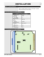
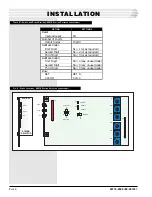
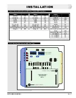
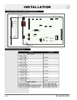
Refer to Tables A through D and Figs. 3 through 7 to set the
straps and switches on the modules.
T
ABLE
A - S
WITCH
AND
S
TRAP
S
ETTINGS
, 44020 DTMF D
ECODER
OPTION
Input Impedance
Bridging
Input Level
0 to -20 dBm
Dial Tone Filter
In
Dialing
12-digit
Auxiliary Output
* and #
* or A
Nonlatching
# or C
Nonlatching
SETTINGS
BRDG
0
DTF IN
12 DGT
#2, *2, #1, *1
PLS
PLS
F
IG
. 3 - S
WITCH
AND
S
TRAP
L
OCATIONS
, 44020 DTMF D
ECODER
INSTALLATION
1
12
J1
1
12
J2
C2
#2
A2
2
C1
#1
A1
1
16
DGT
12
0DB
+10DB
-10DB
IN
DTF
OUT
BRDG
600 OHM
OR A
# OR C
CLR
EXT
CLR
PLS
EXT
CLR


