background image

P

AGE

 28

05725-02-0499 <90-00201>

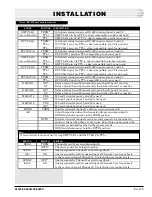
MODULE

46009 Multiple Alarm Transmitter

46009 Multiple Alarm Transmitter

46028 Control Point Module

46020-38 Multiple Alarm Processor

49029 RS-232 Subassembly

46033 E-System Adapter

49013 Tone Modem

4003C DST

46105 64 kB Dual VF Channel

46019 Summary Alarm Module

48001 Fuse Module

SLOT

1

2

5

7

7

8

8

9

10

11

12

SUMMARY OF DEFAULT SWITCH SETTINGS

Addresses 17 and 18 (E-System display 5, bits 1-32); DCM

protocol; 9600 baud; display function set for alarms with

levels; transmit of data in response to poll; no input alarm
reversals; alarm inputs set for latching; alarm points latch

release automatic on poll.

Addresses 19 and 20 (E-System display 5, bits 32-64); DCM
protocol; 9600 baud; display function set for alarms with

levels; transmit of data in response to poll; no input alarm

reversals; alarm inputs set for latching; alarm points latch
release automatic on poll.

No subassembly; 9600 baud; relays set for long momentary

(3 seconds); address 1; latch release set for normal; CA/CF
reversal (S3) set for normal; watchdog circuit strap set

for A.

CPM-Echo off; memory battery backup off initially, then on
when system configured; extended addressing off; printer

port set for printer syntax, 9600 baud; master port set for

DCP protocol, address 1, E-system mode on, 1200 baud; data
port set for 9600 baud, DCM protocol, no TBOS.

S1 set for -00 (normal mode); CTS not used (X1 on); DCD not

used (X2 on); parallel option off (X3 to 1 & 2).
E-System address 1; set to poll one MAP; E2A protocol; delay

setting on; 1200 baud data rate; second address disabled;

DCP polling rate set to 1200 baud; configuration for address
1 set to 32 (all displays set for L142).

XMT and RCV set for no master/slave operation; RCV pad

set in (0 to -20 dBm input); XMT pad set to in (-20 to -40
dBm output; S2 set for -00 option (normal); reset/default

jumper set for default.

XMT pad totals 0 dB; RCV pad totals 0; loopback fre-
quency set for 2713 Hz; loopback level set for 23 dB. 2713

factory default. Set per Engineer’s instructions.

Repeater mode; M Lead active; E Lead inactive; RCV data,
XMT data, RCV CLK, and XMT CLK all set for RS-422

terminated; VF bridge switch (S1) set for RPTR; LPBK 1

(S2) off; LPBK 2 (S101) off; test tonelevel set for +7 RCV and
-16 XMT; data levels set for -29 dBm XMT and -6 dBm RCV.

All levels set to latch with alarms; visual alarm indicator

must be acknowledged; audible relay output cutoff set for .5
seconds.

Set for redundant power feeds.

INSTALLATION

S

UMMARY


OF

 S

WITCH

 S

ETTINGS

Table O documents what the application switch settings for the

05725-02 shelf do.

T

ABLE

 O - S

UMMARY


OF

 S

WITCH

 S

ETTINGS

Summary of Contents for B15-00459-02

Page 1: ...a banner in the right margin UPDATED Table of Contents Ordering Information 2 General Description 2 Installation 5 Turn Up Procedure 29 Support Documentation 41 Warranty 42 xmt out loop mon 4003C line...

Page 2: ...drawing that accompanies this Application Manual The 02 option is equipped with a 46105 Dual VF 64 kilobit Chan nel Module The output of this shelf is a digital signal that can be transmitted over a...

Page 3: ...ster Port is used to report the alarm information to the alarm center through the E System Adapter The Master Port provides mounting for the RS 232 subassem bly E System Adapter ESA slot 8 The ESA pro...

Page 4: ...A B C D 1 2 3 4 5 6 7 8 9 10 11 12 13 14 15 16 A B C D A1 A2 RST ACK A1 ON XMT DATA RCV DATA 46009 0X 32 POINT TRANSMITTER 1 2 3 4 5 6 7 8 9 10 11 12 13 14 15 16 A B C D 1 2 3 4 5 6 7 8 9 10 11 12 13...

Page 5: ...labs 4003C 46105 Dual VF 64 kilobit Channel 46019 Summary Alarm Module 48001 Fuse Module 4 Summary of Switch Settings EQUIPMENT MOUNTING Tools Required Ohmmeter Phillips screwdriver 7 16 Nutdriver or...

Page 6: ...1 25 1 16 TB 1 16 TB 15 30 15 30 C1 C2 C3 C4 TB 1 2 3 4 5 6 7 8 9 10 A B E F C5 C6 C7 C8 C1 C2 C3 C4 PANEL D PANEL C PANEL B PANEL A DC GND 1 1 1 1 1 25 50 26 XMIT REC LINE ZAET Circuit LIST 13 CABLS...

Page 7: ...frame rail 4 Place ESD label next to the ESD stud 5 From the rear of the bay install the other ESD stud and lockwasher into the frame rail next to the equipment shelf Secure tightly ensur ing proper...

Page 8: ...C 2D 3A 3B 3C 3D CPM TB A 5B 5D 5A 5C 29 30 MAT MAT WIRING ADDED WHEN PANEL IS NOT EQUIPPED WITH A MAC CARD 1 2 3 4 5 6 7 8 9 1 0 A B C D E F TB A T E R M I N A L S T R I P B A C K P L A N E I N P A N...

Page 9: ...46009 Multiple Alarm Transmitter MAT Refer to Fig 5 and Table A FIG 5 46009 MAT SWITCH AND STRAP LOCATIONS INSTALLATION 1 2 3 4 1 2 3 4 5 6 7 8 1 2 1 2 3 4 5 6 7 8 1 2 3 4 5 6 7 8 BOTTOM EDGE S5 S4 S...

Page 10: ...that the switch is down down ON DCM addresses 17 18 display 5 bits 1 32 DCM addresses 19 20 display 5 bits 33 63 NOTE The MATs in slots 1 and 2 are not interchangeable without changing the address on...

Page 11: ...3 4 5 6 7 8 1 0 0 0 0 0 0 0 1 1 1 1 1 1 1 1 Leave in NORM Leave in A position 46020 38 Multiple Alarm Processor MAP Refer to Figs 7 and 8 and Tables C and D FIG 7 46020 MAP SUBASSEMBLY AND SWITCH LOCA...

Page 12: ...n remove power and place switch 5 position 7 DOWN This will retain the configuration in memory TABLE C SWITCHES 1 THRU 4 46020 38 SWITCH SW5 SW6 SW7 POSITION 1 2 3 4 5 6 7 8 1 1 1 1 1 1 0 1 1 1 1 1 1...

Page 13: ...Normal Position TXD RXD RTS and DCD reversed CTSusedforhandshaking CTS not used for handshaking DCDusedforhandshaking DCD not used for handshaking ParallelOption YES NO SWITCH OR STRAP SETTINGS S1 00...

Page 14: ...Table F 1 0 1 0 0 0 0 0 0 1 1 1 1 1 1 1 NOTE A 1 indicates that the rocker switch is up adjacent to the position number open OFF A 0 indicates that the rocker switch is down adjacent to the position...

Page 15: ...1 0 0 0 0 0 0 0 1 0 0 1 0 0 0 0 1 0 1 0 0 0 0 0 1 0 1 1 0 0 0 0 1 1 0 0 0 0 0 0 1 1 0 1 0 0 0 0 1 1 1 0 0 0 0 0 1 1 1 1 0 0 0 1 0 0 0 0 0 0 0 1 0 0 0 1 0 0 0 1 0 0 1 0 0 0 0 1 0 0 1 1 0 0 0 1 0 1 0 0...

Page 16: ...0 0 1 0 0 1 0 0 0 1 0 0 0 1 0 0 0 1 1 0 0 1 0 0 1 0 0 0 0 1 0 0 1 0 1 0 0 1 0 0 1 1 0 0 0 1 0 0 1 1 1 0 0 1 0 1 0 0 0 0 0 1 0 1 0 0 1 0 0 1 0 1 0 1 0 0 0 1 0 1 0 1 1 0 0 1 0 1 1 0 0 0 0 1 0 1 1 0 1 0...

Page 17: ...0 1 1 0 1 0 1 1 1 0 0 0 1 0 1 1 1 0 1 0 1 0 1 1 1 1 0 0 1 0 1 1 1 1 1 0 1 1 0 0 0 0 0 0 1 1 0 0 0 0 1 0 1 1 0 0 0 1 0 0 1 1 0 0 0 1 1 0 1 1 0 0 1 0 0 0 1 1 0 0 1 0 1 0 1 1 0 0 1 1 0 0 1 1 0 0 1 1 1 0...

Page 18: ...0 1 0 0 0 0 1 1 1 1 0 0 0 1 0 0 0 1 0 0 0 1 0 0 1 1 0 0 0 1 0 1 0 1 0 0 0 1 0 1 1 1 0 0 0 1 1 0 0 1 0 0 0 1 1 0 1 1 0 0 0 1 1 1 0 1 0 0 0 1 1 1 1 1 0 0 1 0 0 0 0 1 0 0 1 0 0 0 1 1 0 0 1 0 0 1 0 1 0 0...

Page 19: ...0 1 0 1 1 0 0 1 1 1 0 1 1 0 1 0 0 1 0 1 1 0 1 0 1 1 0 1 1 0 1 1 0 1 0 1 1 0 1 1 1 1 0 1 1 1 0 0 0 1 0 1 1 1 0 0 1 1 0 1 1 1 0 1 0 1 0 1 1 1 0 1 1 1 0 1 1 1 1 0 0 1 0 1 1 1 1 0 1 1 0 1 1 1 1 1 0 1 0 1...

Page 20: ...0 1 1 1 1 1 1 1 1 0 0 0 0 0 1 1 1 0 0 0 0 1 1 1 1 0 0 0 1 0 1 1 1 0 0 0 1 1 1 1 1 0 0 1 0 0 1 1 1 0 0 1 0 1 1 1 1 0 0 1 1 0 1 1 1 0 0 1 1 1 1 1 1 0 1 0 0 0 1 1 1 0 1 0 0 1 1 1 1 0 1 0 1 0 1 1 1 0 1 0...

Page 21: ...e only TABLE G CONTINUED 46033 E SYSTEM ADAPTER S2 SWITCH SETTINGS 49013 202 Tone Modem Subassembly Refer to Fig 11 and Table H for switch and strap settings FIG 11 49013 202 TONE MODEM SWITCH AND STR...

Page 22: ...ON S2 OFF 1 2 1 2 3 4 OFF 5 Transmit and Receive channel level switches are located on front panel Note that the settings shown are factory settings Change per Engineer s instructions IN IN 1 2 4 8 1...

Page 23: ...FF 1 ON refer to Table J OFF ON FRONT PANEL LEVEL SWITCHES XMT 0 dB refer to Fig 12 RCV 0 dB refer to Fig 12 TABLE I 4003C SWITCH OPTIONS TABLE J 4003C LOOPBACK FREQUENCY SELECTION S13 FREQUENCY 2813H...

Page 24: ...L TM T T TM T T TERM RPTR S101 S2 S1 T T L T E R M RCV DATA T T L T T L T E R M RCV CLK T T L T T L T E R M XMT CLK Y E S N O M LEAD N C N D E LEAD 46105 Dual VF 64 Kilobit Channel Refer to Fig 13 and...

Page 25: ...is TTL compatible pin 44 is not used 180 ohm termination across RS 422 inputs at pins 5 and 6 XMT CLK 2 pin 5 is TTL edge compatible pin 6 is not used XMT CLK 2 pin 6 is TTL edge compatible pin 5 is...

Page 26: ...to scale SWITCH 1 2 3 4 POSITION ON Timeout 0 5 min ON Timeout 1 0 min ON Timeout 4 0 min ON Timeout 8 0 min Setting for this application All switches OFF no timeout Only one switch may be on at a ti...

Page 27: ...01 01 REV __ Alarm 1 2 3 4 5 6 7 8 9 10 11 12 JP1 1 2 3 POSITION Pins 1 2 Pins 2 3 DESCRIPTION RedundantorSingleInput TwoIndependantInputs Setting for this application 48001 Fuse Module Refer to Fig 1...

Page 28: ...inter syntax 9600 baud master port set for DCP protocol address 1 E system mode on 1200 baud data port set for 9600 baud DCM protocol no TBOS S1 set for 00 normal mode CTS not used X1 on DCD not used...

Page 29: ...0062 00 DB 15 M M cables between C1 and C2 and the fiber optic terminals 4 Mount the A25 00710 00 frame block on a frame or use the A25 00508 01 23 Block mounting bar to mount the cross connect block...

Page 30: ...k These levels need not be changed unless they are not within the 1 dB tolerance but they should be verified on the routine level maintenance schedule FIG 16 TONE LEVELS CONTINUED Dantel TELLABS 4003C...

Page 31: ...be required to verify suspected bad modules or to set levels on modules that have been swapped out SLOTS 1 AND 2 MULTIPLE ALARM TRANSMITTER MAT NOTE Slots 3 and 4 are wired only and not equipped The...

Page 32: ...Z D 4 TELLABS 4003C 46020 40 XMT DATA 49029 00 RS232 XMT DATA RCV DATA RTS DCD DTR CTS Not Used LEDs will be on 46105 XX DUAL VF 64B CHAN XMT 46105 XX RCV SYNC RCV LVL GND XMT RCV SYNC RCV LVL GND Syn...

Page 33: ...to 64 and observe the MAT alarm LEDs The corresponding LED on the MAT should light up whenever the alarm input of the A25 00710 00 block is grounded MAT 1 is for alarm inputs 1 to 32 and MAT 2 is for...

Page 34: ...o the CPM and that all of the points are now released This will turn off all control points 5 Observe the CPM LEDs from 1 through 16 they should now be off 6 Use the ohmmeter again and check all contr...

Page 35: ...ace the MAP with a 49029 subassem bly on it with a known good one that has the switches set cor rectly per the Tables Changing Default Alarm Levels All alarms default to a D level If it is necessary t...

Page 36: ...To see if the devices are correctly loaded type MAT MAT address SHOW Or in this case MAT 5 SHOW The MAT level assignment will come back as follows MAT 5 OPTIONS A A A A A A A A A A A A A A A A NOTE A...

Page 37: ...een changed during shipment NOTE The following steps should be only be used to verify the level settings They should only be required if modules are swapped or to test suspected bad modules 1 Using a...

Page 38: ...e used to only verify the level settings They should only be required if modules are swapped out or to test suspected bad modules 1 Refer to Fig 4 and set the bridge terminal switch to terminal Set th...

Page 39: ...ated 1 kHz signal into the DROP XMT jack for channel 2 on the front panel of the 46105 module 16 Verify with the dB meter not terminated a level of 0 dB at both XMT LVL test point jacks for channel 1...

Page 40: ...5 Replace the blown fuse with a good one the short should be removed and the LED should be off GENERALTROUBLESHOOTING If difficulties are experienced with this unit check the following as appropriate...

Page 41: ...DANTEL Included in this section 46020 38 Installation and Operation Manual B18 05725 XX Block and Level Drawing DJ 05725 Ordering Guide an RMA number Include a description of the malfunction with the...

Page 42: ...en instrument signed by a duly authorized officer of the Seller and accepted by the Buyer Warranty and remedies on products not manufactured by the Seller are in accordance with warranty of the respec...

Reviews: