P
AGE
32
05725-02-0499 <90-00201>
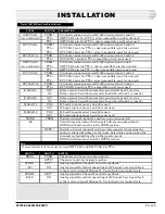
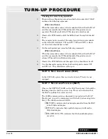
TURN-UP PROCEDURE
F
IG
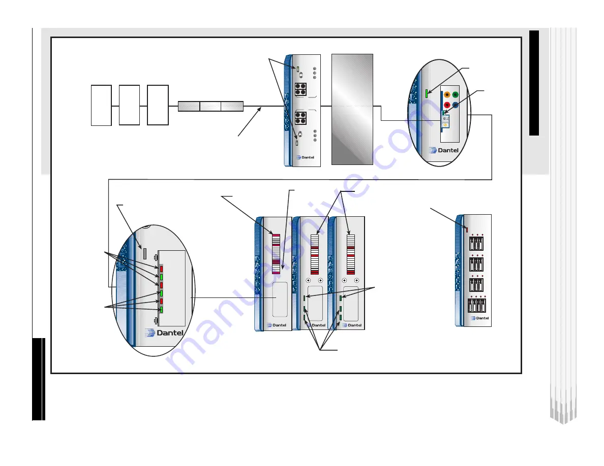
. 17 - 05725 LED
S
CONTINUED
. . .
DATA
XMT
46033-00 REV__
B12-49013-00
T
E
S
T
RCV
XMT
XMT
LVL
TONE
MODEM
CD
46009-00
Multiple Alarm
Transmitter
RST
A1
A2
ACK
A1
TX
RX
1
2
3
4
5
6
7
8
9
10
11
12
13
14
15
16
A
B
C
D
1
2
3
4
5
6
7
8
9
10
11
12
13
14
15
16
A
B
C
D
46009-00
Multiple Alarm
Transmitter
RST
A1
A2
ACK
A1
TX
RX
1
2
3
4
5
6
7
8
9
10
11
12
13
14
15
16
A
B
C
D
1
2
3
4
5
6
7
8
9
10
11
12
13
14
15
16
A
B
C
D
XMIT RCV and
RTS LEDs
means the MAP
is communicating
with the E-System
Adapter
XMT to Data to CPM/MAT
MAP
CPM
MAT
MAT
E-SYS
ADAPTER
Data sent to
TNC
Carrier received
from TNC
46033
T
N
C
K
Z
Z
D
4
TELLABS
4003C
46020-40
XMT DATA
49029-00
RS232
XMT
DATA
RCV
DATA
RTS
DCD
DTR
CTS
Not Used
LEDs will
be on
46105-XX
DUAL VF
64B CHAN
XMT
46105-XX
RCV
SYNC
RCV LVL
GND
XMT
RCV
SYNC
RCV LVL
GND
Synch LEDs
indicate when
device is in sync
with remote 46105
46105
Remote
C18-05724-XX
64KB Channel
4
5
6
7
8
9
10 11 12 13
B11-48001-01 REV.
48001-01
Fuse Module
Alarm
1
2
3
CH 1
Control LEDs mean
the CPM is receiving
control commands
Indicates the CPM
is communicating
with the MAP
XMIT and REC data means
the MAC is communicating
with the MAT
A1 LED on/off
every 6 seconds
means:
A1 On=Alarms 1-16
A1 Off=Alarms 17-32
functioning properly
Alarm LEDs mean the MAT
is receiving discrete alarms
Blown fuse
indicator
Fuse
Module
-02 Option
46028-02
Control Point
Module
1
2
3
4
5
6
7
8
9
10
11
12
13
14
15
16
RX
TX
CH 2
RCV
MON DROP
XMT
RCV
XMT
MON DROP
46105


