31
975672 •
Ver
s
ion
3.3 •
28.1
0
.201
0
Hygrostat and other control options,
continued
Defrosting
If the CDP 75/125/165 are used in the temperature range between 15 and 20°C the
evaporator coil should be protected by a sensor.
When the defrosting sensor registers a temperature below 5°C, the control interprets
this as ice building up on the evaporator coil and lets the unit run for another 30 min-
utes. Then the compressor stops and the fan leads the room air over the evaporator
coil until the defrosting sensor registers that the temperature has reached 5°C.
This defrosting process is called passive, demands-related defrosting, as it only takes
place when needed.
The defrosting sensor is supplied on demand as an extra accessory. A mounting in-
struction follows the defrosting sensor.
Connection of
defrosting sensor
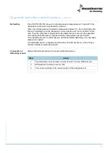
Please follow this procedure to connect a defrosting sensor:
Step
Action
1
The defrosting sensor is fixed in points 15 and 16 on the PCB terminal
2
DIP Switches 3 and 6 are set on ON
3
The sensor is placed in the sensor pocket of the evaporator coil
Summary of Contents for cdp 75
Page 74: ...74 74 75 77 79 o 82 84 89 90 91...
Page 77: ...77 975672 Version 3 3 28 10 2010 CDP 75 125 165 CDP 75 125 165 5...
Page 79: ...79 975672 Version 3 3 28 10 2010...
Page 80: ...80 OFF ON 7...
Page 81: ...81 975672 Version 3 3 28 10 2010 u1080...
Page 82: ...82 o 12 1 3 4 a 12 1 5 6 2 5 6...
Page 83: ...83 975672 Version 3 3 28 10 2010 o CDP 75 125 165 15 20 5 30 5 1 15 16 2 DIP 3 6 ON BK...
Page 84: ...84 CDP 75 125 16 CDP 75 CDP 125 t 3 4 0 5 2 u1086...
Page 87: ...87 975672 Version 3 3 28 10 2010 CDP 75 125 165 15 PEX 112 IN OUT 121...
Page 89: ...89 975672 Version 3 3 28 10 2010 1 2 3 1 1 2 3 1 2 3 4 5...


