37
INSTALLATION & SERVICE MANUAL FOR PROFESSIONALS
Installation
: Calibration of airflow
en
Calibration of airflow
In order to achieve the correct comfort level, as well as to control humidity levels, it is import-
ant to adjust the amount of supply air entering the house, as well as the exhaust air from the
house.
This is done by adjusting the fan speed level in a nominal mode corresponding to level 3.
Calibration of the airflow can be done in two ways:
1. via the membrane keypad on the unit (see description below)
2. via PC Tool (follow the step-by-step description in PC Tool)
In both procedures, the airflow must be calibrated by measuring ΔPa over the heat exchanger
using the pressure nozzles behind the front plate.
Dantherm recommends a handheld manometer, such as Testo 510 or similar.
Pour 0.5 L water into the water trap to prevent leakage from the drain prior to calibration.
Follow these steps in preparation for calibrating the device.
Step Action
Illustration
1
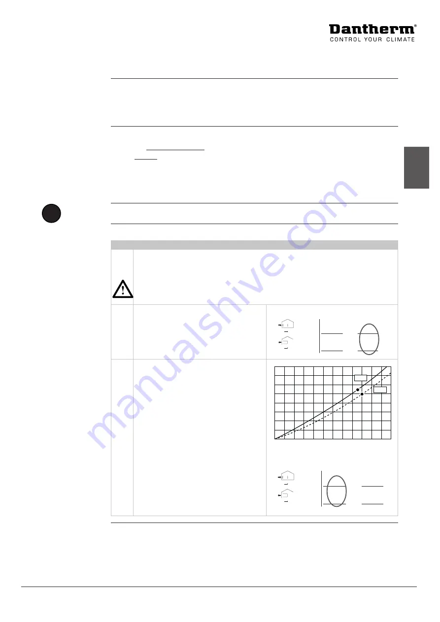
Use the desired airflow rate according to national regulations that corresponds to
the size and pressure drop of the house.
The supply airflow must under no circumstances be higher than the exhaust airflow,
as this can lead to humid air being pressed into the building structure with harmful,
negative effects on the building.
2
Note the desired values for supply and
exhaust airflow rates on the label located
on the cover of the heat exchanger.
(The values shown are examples for illus-
trative purposes only)
Airflow
Einstellwerte / Calibration / Calibrazione
0
20
30
10
40
60
80 100 120 140 160 180 200 220 240
40
50
60
70
80
20
0
[Pa]
[m³]
[m³]
[Pa]
P1 P2
P3 P4
P1-P2
P3-P4
Airflow
Einstellwerte / Calibration / Calibrazione
0
20
30
10
40
60
80 100 120 140 160 180 200 220 240
40
50
60
70
80
20
0
[Pa]
[m³]
[m³]
[Pa]
P1 P2
P3 P4
P1-P2
P3-P4
Airflow
Einstellwerte / Calibration / Calibrazione
0
20
30
10
40
60
80 100 120 140 160 180 200 220 240
40
50
60
70
80
20
0
[Pa]
[m³]
[m³]
[Pa]
P1 P2
P3 P4
P1-P2
P3-P4
171
180
3
Locate the corresponding pressure drop
on the airflow graph on the heat ex-
changer and note the value as shown.
Airflow
Einstellwerte / Calibration / Calibrazione
0
20
30
10
40
60
80 100 120 140 160 180 200 220 240
40
50
60
70
80
20
0
[Pa]
[m³]
[m³]
[Pa]
P1 P2
P3 P4
P1-P2
P3-P4
Airflow
Einstellwerte / Calibration / Calibrazione
0
20
30
10
40
60
80 100 120 140 160 180 200 220 240
40
50
60
70
80
20
0
[Pa]
[m³]
[m³]
[Pa]
P1 P2
P3 P4
P1-P2
P3-P4
Airflow
Einstellwerte / Calibration / Calibrazione
0
20
30
10
40
60
80 100 120 140 160 180 200 220 240
40
50
60
70
80
20
0
[Pa]
[m³]
[m³]
[Pa]
P1 P2
P3 P4
P1-P2
P3-P4
171
180
50
54
Introduction
Calibration tools
!
NOTE
Use of graph
Warning
Caution
Summary of Contents for HCV 300
Page 1: ...HCV 300 400 460 500 700 MANUAL en Rev 1 2 2021 W03 4...
Page 2: ......
Page 58: ......
Page 59: ......


