background image


 U:\Manuals\EFC\EFC2V2TC 

-EN-.pdf 

10/15                                                           2008-11-13 

Preventive maintenance 


Introduction 

The unit needs preventive maintenance with specific intervals to avoid breakdown or 
inefficient operation. It is important to notice that interval between maintenance can 
vary depending on the specific environment. 

Caution! 

Switch off the AC supply before working on the unit! 

Make sure that all work has been performed before switching on the power again. 

Service function 

“Timer” 


The controlling unit has a service function to ensure better indoor climate for 20 
minutes during the presence of service technicians. To activate the service function, 
push one step up from the main menu to find “Timer”. Now press “Enter”. The control 
unit will now count down from 20 and then go back to normal operation. 

Interval 

Kontrollelektronik Dantherm Air Handling AB recommends that intervals between 
preventive maintenance do not exceed 1 year. It is also our recommendation that the 
site and unit is examined closely during the first preventive maintenance to determine 
whether the interval is too long. We recommend that preventive maintenance visits are 
planned to occur in springtime. 

Condition for 
warranty 

The factory warranty is only valid if documented preventive maintenance has been 
carried out with an interval of maximum 1 year. The documentation could be in form of 
a written log. 

Leaving the site 

Before leaving the site, make sure there are no alarms! 

Recommended 
approach 

The recommended approach when performing a preventive maintenance visit is: 


Step 

Action 

Make sure that the power to the unit is safely switched off. 

Remove the worn-out filter and clean the unit carefully. 

Clean the dampers and check them regarding function and tightness. 

Clean the fan and check its mounting. 

Check and clean the air intake and exhaust accessories. 

Insert the new filter carefully into the unit. 

Close the unit and make sure that the service is completed correctly. 

Turn on the power to the unit. 

Run the Self test according to the separate manual for the controller. 


Function tests 

Fan and filter alarm function tests can be done by the following actions. 


Function test 

Action 

Filter 

Open the service door and put a plate of carton or similar on the 
intake side of the filter, blocking a big part of the filter area. Close the 
service door, run the free cooling unit and check that filter alarm is 
given. Stop and remove the plate. 

Fan 

Open the lid to the controlling unit and remove the brown cable 
connected to the connector marked “TK1”. Close the lid, run the free 
cooling unit and check that fan alarm is given. Restore the controller. 


Summary of Contents for KONTROLLELEKTRONIK EFC2 V2 TC

Page 1: ...U Manuals EFC EFC2V2TC EN pdf 1 15 2008 11 13 EFC2 V2 TC Service manual...

Page 2: ...0 Spare parts list 11 Test Report TKS 3000 and ACUE 3000 12 Test Report ACUE CS1 14 Contact In the table below you can see how to contact the manufacturer and sales offices Office Sweden Norway Denmar...

Page 3: ...ltage Directive including 93 68 EEC where required 86 336 EEC EMC Directive including 92 31 EEC and 93 68 EEC 89 392 EEC Machine Directive The product is manufactured according to SS EN 604 39 1 The p...

Page 4: ...ons with frame WxHxD 720x720x656 720x720x656 Cabinet data Data and dimensions of the cabinet are shown in the following table Specification Designation Value Weight Estimated to max 45 kg Metal sheet...

Page 5: ...Controlling The table below show the components and types for controlling of the Free cooling unit Specification 48 VDC 48V DC 230V AC Control unit See separate manual ACUE CSI 3GS ACUE 3000 TKS 3000...

Page 6: ...ATURE SET MOTOR PROTECTOR SET COOLING UNITS 0 1 2 SET HIGH TEMP ALARM SET CONTROL MODE SET LOW TEMP ALARM OUTDOOR TEMPERATURE SET TEMP EL HEATER SET DIFF TEMP COOLING 1 SET DIFF TEMP COOLING 2 MODE SE...

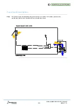
Page 7: ...ption Flow The picture below schematically shows the air flow in a shelter In the same picture some accessories that can be connected to the controller are shown GT1 EFC2 V2 230 V RADIOBASE SHELTER GT...

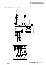
Page 8: ...een Brown Blue Yellow green Brown White Indoor temp sensor RG TD5A Exhaust Air damper 230VAC LM230A 3 x 0 5 Brown Green White 2 Brown 3 White 1 Blue Junction box Brown Green White Filter Alarm Output...

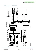
Page 9: ...hite 3 5 4 Brown 1 2 Black Blue 5G 1 5 1 Black Blue Green yellow White Brown PB2 F12 Brown White Brown White SENSOR RG K81 PUSH BUTTON TIMER OPTION 2x0 5 OUTDOOR TEMP SENSOR SG K81 White Brown 3 2 Fno...

Page 10: ...valid if documented preventive maintenance has been carried out with an interval of maximum 1 year The documentation could be in form of a written log Leaving the site Before leaving the site make sur...

Page 11: ...4 Damper actuator LM230 889 331570 Damper actuator LM24 889 331562 Contact In the table below you can see how to contact the manufacturer and sales offices Office Sweden Norway Denmark Name Kontrollel...

Page 12: ...er activated if installed Check that the heater becomes warm 2 120 Air dampers to environment open if installed Check that the air damper opens 3 60 Fan signal speed up to max Check that the fan speed...

Page 13: ...ble shall be done Alarm Action Check Fire smoke alarm Activate the smoke detector Check that everything is stopped Fan Heater AC and that the dampers are closed The display shows Fire Alarm Sign the p...

Page 14: ...ime delay The test can be stopped whenever you wish by pressing the button approximately 5 seconds or until the display show any form of a two figure number The designations in the protocol refer to t...

Page 15: ...TEMP ALARM The sensor indicate very hot cut off or not connected To make the test of the sensors as reliable as possible please make no manual steps After the self test the Fire and smoke alarm if ap...

Reviews: