background image

Overview

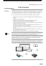
This Manual describes the installation and use of the “Simplify” monitoring solution .

The Manual item number is: 055068 .

The target group for this product comprises fitters, technicians as well as end-users, who need to 

monitor a dehumidification process and require data within a given time frame from a location 

presented online . (Temperature, humidity, air quality, power consumption and so on) .

The devices must only be installed and repaired by qualified personnel . 

It is the fitter’s, technician’s and user’s responsibility to read and understand this Manual prior to 

initial setup and start-up of the devices .

The devices are not intended for use by persons (including children) with impaired physical, 

sensory or mental capabilities, unless they are supervised or have received instructions in the use 

of the device by a person responsible for their safety .
Children must be supervised to ensure they do not play with the device .

Any form of maintenance other than external cleaning of the device must be performed by 

trained personnel .
The protection class for the devices is defined in the section on “IP class, description” on page 

27 .

The Manual or parts thereof may not be copied without Dantherm’s prior written consent .

Dantherm reserves the right to make changes and improvements to the product and the manual 

at any time and without prior notice or obligations .

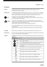
The following symbols are used in this manual to draw attention to hazards and further relevant 

information .

Warning and
explanatory symbols

Warning

Caution

WARNING

This symbol in conjunction with the word “Warning” warns of the risk 

of severe personal injury .

Warning

Caution

CAUTION

This symbol in conjunction with the word “Caution” warns of the risk 

of minor or moderate personal injury and property damage .

!

NOTE!

The symbol is used in connection with tips and information on the use 

of the device .

The symbol is used in connection with descriptions/explanations .

The symbol is used in connection with step-by-step actions .

The symbol is used in connection with a problem

The symbol is used in connection with a suggested solution

The symbol is used in connection with troubleshooting

The symbol is used in connection with functional descriptions

Manual

Target group

!

NOTE!

Warning

Caution

WARNING

Copyright

Reservations

Symbols 


Introduction

: Overview

 4

Summary of Contents for SIMPLIFY

Page 1: ...en Rev 1 0 2021 W21 4 USER MANUAL SIMPLIFY MONITORING CONTROL SYSTEM...

Page 2: ...o responsibility for possible errors and changes en Der tages forbehold for trykfejl og ndringer da Irrt mer und nderungen vorbehalten de Dantherm n assume aucune responsabilit pour erreurs et modific...

Page 3: ...uction 9 Installation 11 System setup 11 Extending replacing a Sensor Box in an active installation 12 Replacing a Sensor Probe in an active installation 12 Use 13 Use of CDT Dehumidifiers with Integr...

Page 4: ...for the devices is defined in the section on IP class description on page 27 The Manual or parts thereof may not be copied without Dantherm s prior written consent Dantherm reserves the right to make...

Page 5: ...er can then be controlled from the Dashboard Simplify Sensor Probe Sensor Probe that measures temperature and relative humidity Probes are available in the following lengths 24 cm 300 cm 2 000 cm Simp...

Page 6: ...azardous to human health and the environment if the waste is not managed properly It is important that end users dispose of all end of life batteries using established recycling schemes This makes sur...

Page 7: ...on and is manufactured in conformity with the following harmonised standards EN62368 1 2020 Audio video information and communication technology equipment Part 1 Safety requirements EN 301 489 1 V2 1...

Page 8: ...for best ease of use we recommend the use of not more than 50 Sensor Boxes Simplify will automatically start the CDT Dehumidifier once the Control Unit has established connection If the 230 V supply...

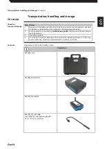
Page 9: ...rding to local regulations 3 Check the contents 4 If any form of transport damage is discovered after unpacking devices or if the ship ment is defective contact your local dealer as quickly as possibl...

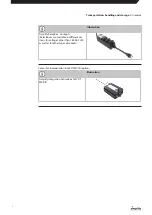
Page 10: ...able in different ver sions for voltages other than 184 265 VAC as well as for other types of sockets Sensor for incorporation into CDT MII III option Illustration Simplify integration Sensor Box for...

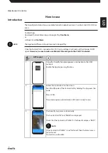
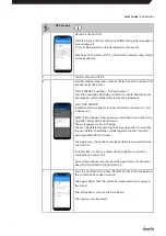
Page 11: ...coverage via the 2G 2 5G network APP Layout 1 Using the Simplify App presupposes a connection to the GSM network Enable the App by pressing the icon 2 Follow the instructions on the screen Scan the Q...

Page 12: ...rom a previous installation are visible in the App the Control Unit is not archived They will appear as a list in the App They can be deleted by pressing the Sensor Box until it is possible to press d...

Page 13: ...ey emit 3 short beeps indicating the connection is okay and that data is received If the 3 beeps are not emitted connection to the Control Unit is NOT established Move the Sensor Box or Control Unit s...

Page 14: ...d the next time the Control Unit up loads data to the Dashboard which happens after a few minutes 3B If the connection is a Sensor Box connected Sensor Probe where the Sensor Box becomes ACTIVE Sensor...

Page 15: ...umidifiers will then be displayed on the Dashboard Power consumption kW and total power consumption kWh are displayed in the Dashboard for each CDT Dehumidifier and for all CDTs together If a CDT has...

Page 16: ...at the selected data interval Sensor Boxes transmit signals to the Control Unit at the interval defined in the Dashboard Battery life depends on the transmission interval and on site radio conditions...

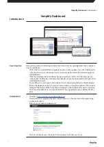
Page 17: ...he office which can then be transported to the address and switched on Clicking MAP opens Google MAP for the area where a Control Unit is scanned and regis tered Driving directions can be generated Yo...

Page 18: ...lick The most recently received data is displayed in the colour field for the respective parameters As a rule each field has a colour selected by the Dashboard It can be edited and is used in the grap...

Page 19: ...ion which means that recipients will be advised if equipment in the installation becomes PASSIVE You can set alarms for individual Sensor Boxes for all parameters HUM TEMP DWT PWR etc It is possible t...

Page 20: ...hat the equipment does not transmit data and for how long In case of ON or OFF action from the button ON in the menu bar the equipment will either turn on or off the next time the Control Unit is in c...

Page 21: ...ard and is ready for a new case REPORT GENERATOR makes it possible to create Word and Excel files containing all data from the Dashboard All data may be freely combined for one several or all sensors...

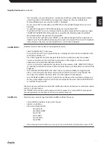
Page 22: ...e to create one or more Supervisors with a general role User level Individual users without rights other than daily use of assigned Control Units Select Admin in the top menu Select Users Enter Userna...

Page 23: ...ta from a Sensor Box can be explained in many ways Check that the Sensor Probe is properly connected to the Sensor Box Sensor Box audio signal 1 beep if battery is OK 2 beeps if battery and Sensor Pro...

Page 24: ...p Store The mobile tablet runs an Android version older than 5 1 or iOS older than iOS 10 Update to an Android version earlier than 5 1 and iOS 10 or earlier No disk space Check that there is enough s...

Page 25: ...de here https support dantherm com or contact Dantherm Intelligent Monitoring A S Kirkebjerg Parkvej 12 Br ndby DK 2605 Denmark Tel 45 70 22 11 20 E mail info dantherm com If you need spare parts cont...

Page 26: ...to 60 Battery service life Year 5 Data Unit Specification Mains voltage VAC 184 264 50 Hz Current total max A 16 Tx power max mW 10 Tx Rx frequency MHz 868 Temperature range storage C 40 to 60 Temper...

Page 27: ...cted against dust i e some dust may enter the product but is must not be destructive Overspray Protected against water spraying against the product from all directions IP 67 Dust proof The material is...

Page 28: ...Dimensions 184 5 173 9 129 9 59 65 66 32 8 95 100 76 72 3 81 200 Control Unit Rotary aerial Sensor Box Relay Box Appendix Dimensions 28...

Page 29: ...95 65 32 8 Sensor Probe Integration Box Appendix Dimensions en 29...

Page 30: ......

Page 31: ......

Page 32: ...KEEP UPDATED FOLLOW US ON danthermgroup com Manufacturers details Dantherm Intelligent Monitoring A S Kirkebjerg Parkvej 12 Br ndby DK 2605 Denmark t 45 70 22 11 20 e info dantherm com 055068 055068...

Reviews: