12
Operation
Read and understand this Owner's Manual carefully before attempting to operate or adjust
the Danuser G20/40 Digger. You are responsible for furnishing this manual to others who
may use the unit. If you have any questions regarding the proper assembly, installation, or
operation of this digger, contact your dealer or Danuser Machine Company, Inc.
STEP 1:
Contact local utility companies to make certain there are no buried gas lines,
electrical cables, etc. in the work area. Clear area of objects that could wrap
around the auger or might be thrown. Check for ditches, stumps, holes, or other
obstacles that could cause the tractor to roll.
STEP 2:
Layout and mark where you want to dig your holes.
STEP 3:
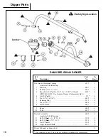
Adjust the auger to a vertical position:
a)
Left to right vertical adjustments -
With the PTO disengaged, raise the auger point off the ground. If the
auger pitches left or right, turn the adjusting screw or leveling crank on the
lifting link until the auger appears vertical when looking from the tractor
seat. Refer to your tractor operating manual for further instructions on
three-point hitch adjustments.
b)
Front to back vertical adjustments -
Lower the auger slowly until the point just touches the ground. Move the
tractor slowly forward or backward until the auger appears vertical when
looking from the tractor seat.
STEP 4:
Set the tractor brakes and take the tractor out of gear to hold the tractor on
location to prevent damage to the digger.
STEP 5:
Slowly lower the auger point to the ground. Make sure the auger point is on the
ground before engaging the PTO.
STEP 6:
Lower the auger into the ground slowly, then increase the speed as required so
the dirt is augured out from the hole. NEVER exceed 540 RPM. In many types
of soil, it may be necessary to hold back against the auger screw suction by
moving the hydraulic control lever momentarily to either the “HOLD” or
“RAISE” position to keep the auger from screwing into the ground.
When mounted to the three-point hitch, your digger must be able to raise and
lower through the highest and lowest points of your lift arm travel without
binding against the tractor frame. If it does bind, adjust the tractor three-point
linkage so that all movement is free.
NOTE
This post hole digger was designed for one-man operation
from the tractor seat. It is the responsibility of the operator
to see that bystanders and all other people are at least
twenty-five feet (25') from the digger in operation or under
power. Serious personal injury or death may result if any
attempt is made to assist digger operation by hand.
D A N G E R
Personal protection equipment including hard hat, safety
glasses, safety shoes, and gloves are recommended during
assembly, installation, operation, adjustment, maintenance,
repair, removal, or movement of the digger. Do not allow
long hair, loose fitting clothing, or jewelry to be around
moving parts.
W A R N I N G
Never position the auger
point by hand or with any
tool when the tractor is
running. Never position
the auger point by putting
your hands on the auger,
gearbox, boom, or
driveline.
W A R N I N G
Serious injury or death
can result from misuse
of this equipment.
C A U T I O N
The G20/40 Digger is
designed for 20 to 40
horsepower, Category I
three-point hitch, 540 RPM
PTO tractors using sway
stabilizers. Auger size
must not exceed 24 inch
diameter. Operation of
this digger in a manner for
which it was not intended
will result in poor
performance and could
create a hazard and the
potential for personal
injury.
W A R N I N G


