


5
button (20). When the button is pushed out its range is from 62 Hz to 850 Hz, and when the button is
pressed down, its range is from 620 Hz to 8.5 KHz.
9. Low Frequency Output Gain
This knob is to adjust the output level of the low frequency signal. The range is fully adjustable from
-
∞
to +12dB.
10. Low Mute Button
Press the button and the low frequency signal has no output and the LED on the left will light up.
11. Mid Frequency Output Level
This knob is to adjust the output level of the Mid frequency signal. The range is fully adjustable from
-
∞
to +12dB.
12. Mid Mute Button
Press the button and the Mid frequency signal has no output and the Led on the left will light up.
13. High Frequency Output Gain
This knob is to adjust the output level of the High frequency signal. The range is fully adjustable from
-
∞
to +12dB.
14. High Mute Button
Press the button and the High frequency signal has no output and the Led on the left will light up.
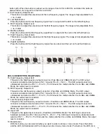
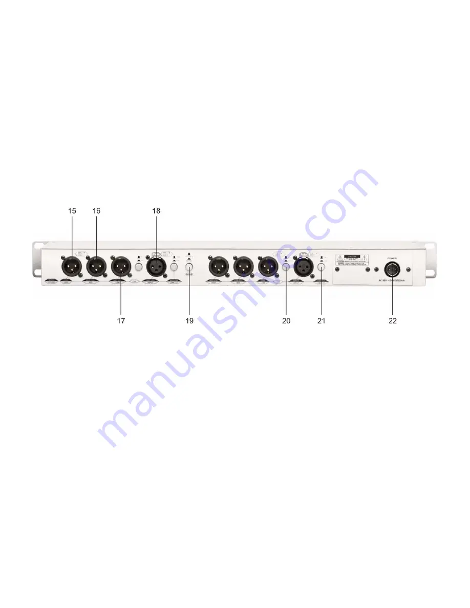
ACX-34 DESCRIPTION REAR PANEL:
15. High Frequency Output XLR
This jack is the high frequency output connector, it has BAL and UNBAL Mode. The XLR output
connector is balanced and wired as Pin 1=Ground, Pin 2=+, Pin 3= -. The XLR output connector is
unbalanced and wired as Pin 1= -, Pin 2=+, Pin 3=Ground. No matter whether it is on BAL and UNBAL
Mode, the output level is constant.
16. Mid Frequency Output XLR
This jack is the mid frequency output connector, it has BAL and UNBAL Mode. The XLR output
connector is balanced and wired as Pin 1=Ground, Pin 2=+, Pin 3= -. The XLR output connector is
unbalanced and wired as Pin 1= -, Pin 2=+, Pin 3=Ground. No matter whether it is on BAL and UNBAL
Mode, the output level is constant.
17. Low Frequency Output XLR
This jack is the low frequency output connector, it has BAL and UNBAL Mode. The XLR output
connector is balanced and wired as Pin 1=Ground, Pin 2=+, Pin 3= -. The XLR output connector is
unbalanced and wired as Pin 1= -, Pin 2=+, Pin 3=Ground. No matter whether it is on BAL and UNBAL
Mode, the output level is constant.
18. Input XLR
This jack is the signal input connector, it has BAL and UNBAL Mode. The XLR input connector is
balanced and wired as Pin 1=Ground, Pin 2=+, Pin 3= -. The XLR input connector is unbalanced and
wired as Pin 1= -, Pin 2=+, Pin 3=Ground. No matter whether it is on BAL and UNBAL Mode, the output
level is constant.
19. Mode Button
With this button you can select whether you want to work in stereo or mono mode. Press the button
and the LED (3) illuminates and the crossover works in 4-way mono mode; Pushed out, the LED (3) is


