

6
off and it works in stereo 3-way crossover mode.
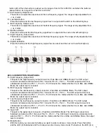
20. Decuple Frequency (x10) Range Button
Press this button, the LED (7) illuminates and the crossover range is from 620 Hz to 8.5 KHz. When the
button is pushed out, the LED is off and its range is from 62 Hz to 850 Hz.
21. 30 Hz Low Cut
Press this button and the signal comes into 30 Hz / 18dB / OCT low cut / high pass filter. It can remove
the harmful signal, such as low frequency hum noise, the strike sound switching ON / OFF the
microphone or the current noise, etc.
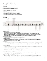
22. Remote Power Supply Input Socket
This is the remote AC power supply input socket for the ACX-34. It is a special three cores socket.
The model for this power supply adapter is “YH-18A-1000”. In order to make your ACX-34 work in a
stable and safe condition, please use this special power supply adapter we provide.
Installation
Remove all packing materials from the ACX-34. Check that all foam and plastic padding is removed.
Screw the equipment into a 19" rack. Connect all cables.
Always disconnect from electric mains power supply before cleaning or servicing.
Damages caused by non-observance are not subject to warranty.
Set Up and Operation
Before plugging the unit in, always make sure that the power supply matches the product specification
voltage. Do not attempt to operate a 120V specification product on 240V power, or vice versa.
Install this device on a flat surface, not bending or curved.
Do not supply power before
all components of the system are
set up and connected properly.
1. Stereo 3-way and mono 4-way combined. Each group frequency is designed with an independent mute
switch.
2. The 24 dB decuple frequency filter provides a sharper crossover frequency and improve the speaker’s
analytic ability.
3. It has a 30 Hz low cut filter removing the low frequency disturb and protecting low speaker.
4. BAL and UNBAL input and output connectors provide constant output level
Stereo and mono modes can easily be set by pushing a switch and connecting Inputs and Outputs properly:
no patch cords required.
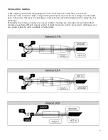
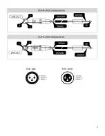
Input and Output
All inputs and outputs are floating and balanced when connected (via a tip, ring.) to other floating and
balanced equipment. Any combination of balanced and unbalanced operation is permitted (see also
“Connection Cables”).