
Ordercode: D1464
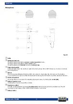
COM-42
Installation
Remove all packing materials from the COM-42. Check that all foam and plastic padding is removed.
Connect all cables.
Always disconnect from electric mains power supply before cleaning or servicing.
Damages caused by non-observance are not subject to warranty.
Set Up and Operation
Before plugging the unit in, always make sure that the power supply matches the product specification
voltage. Do not attempt to operate a 120V specification product on 230V power, or vice versa.
01)
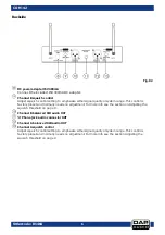
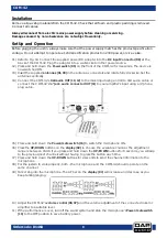
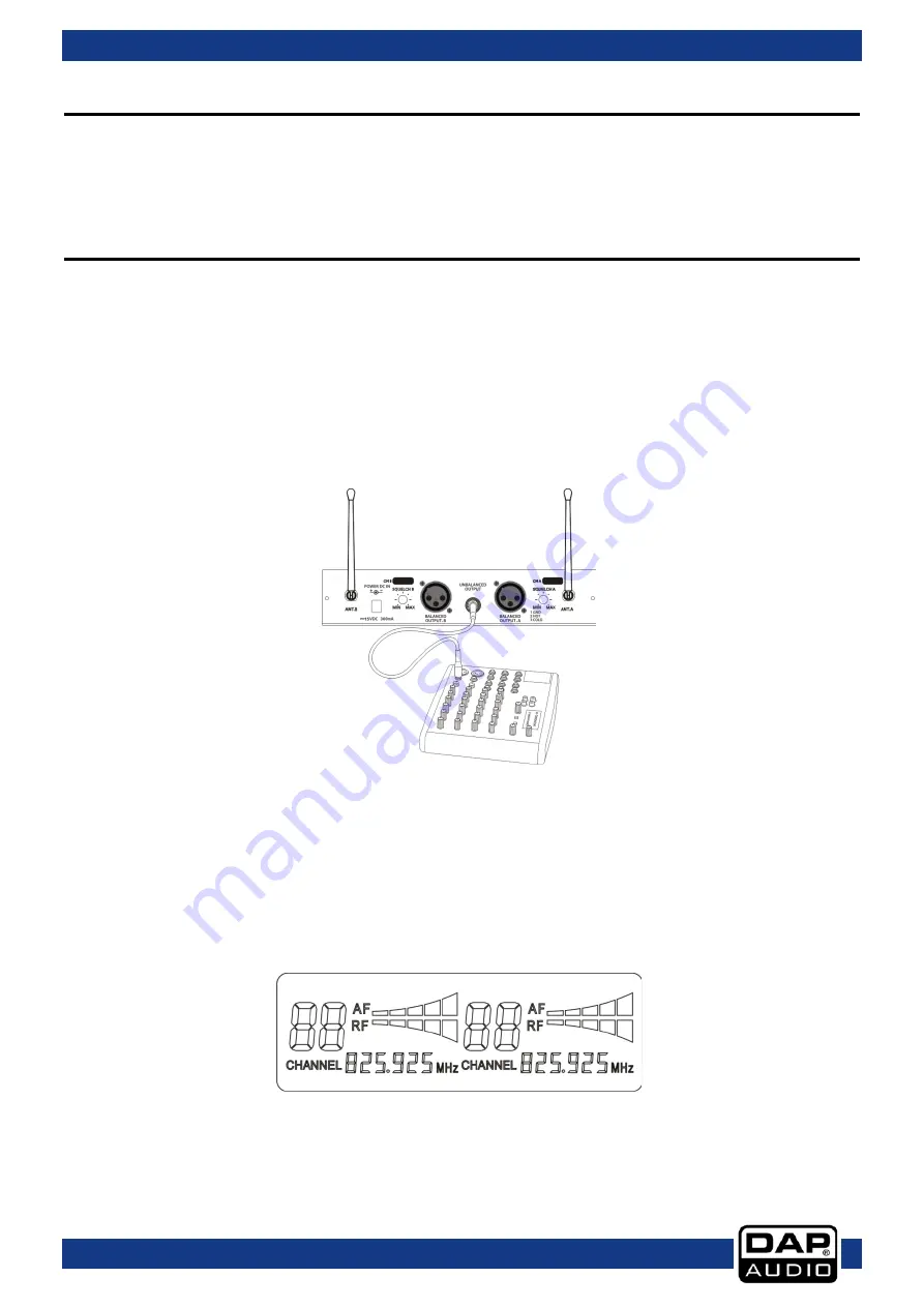
Refer to Fig. 04. Connect the supplied power DC adapter into the DC input Connector (08) at the
back of the COM-42. Plug the adapter into a wall socket or other power source.
02)
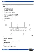
Press and hold down the Power switch (05) on the front of the COM-42 for 4 seconds. The device is
now switched ON.
03)
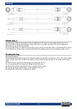
Insert the supplied antennas (01, 03) in the antenna connectors and rotate fully clockwise. Set the
antennas vertically.
04)
Connect the COM-42’s XLR audio OUT (10, 12) to the mixer input using an XLR to XLR audio cable or
connect the COM-42’s ¼” jack audio connector OUT (11) to your amplifier’s input using a ¼”phone
plug cable.
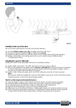
05)
Press and hold down the Power/mute switch (16) to switch the microphone ON.
06)
Press the UP/DOWN buttons on the display (02) to choose the available channel. The adjustment
range is between 00-99. If you press and hold down the UP/DOWN buttons for 8 seconds, you will skip
to the previous/next channels without having to press the button each time.
07)
Press and hold down the UP/DOWN buttons for 2 seconds to send the channel information to the
microphone.
08)
For the system to work properly, both – the microphone and the COM-42, should operate on the
same channel.
09)
Talk or sing into the microphone. The AF bar on the display (02) will increase and decreae as you
keep talking/singing.
10)
Adjust the COM-42’s volume control (06, 07) and the volume adjustment of the connected mixer or
amplifier to a suitable level.
11)
If the performance is over, turn off the sound system and slide the microphone’s Power/mute switch
(16) to the OFF position to save battery power.
8
Summary of Contents for COM-42
Page 15: ...Ordercode D1464 COM 42 14...
Page 16: ...2015 DAP Audio...