


12
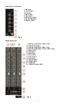
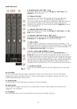
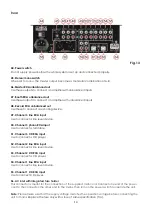
22. Crossfader slope switch
This switch allows the user to select from three types of crossfader curve response.
• At the left setting, the curve produces a rapid signal rise. (As soon as the cross fader lever leaves the
A
side, the
B
channel sound is produced.)
• At the right setting, the curve operates to produce an even, neutral rise throughout the cross fader’s
movement.
• At the middle setting, an intermediate curve is produced, midway between the two curves noted
above.
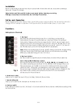
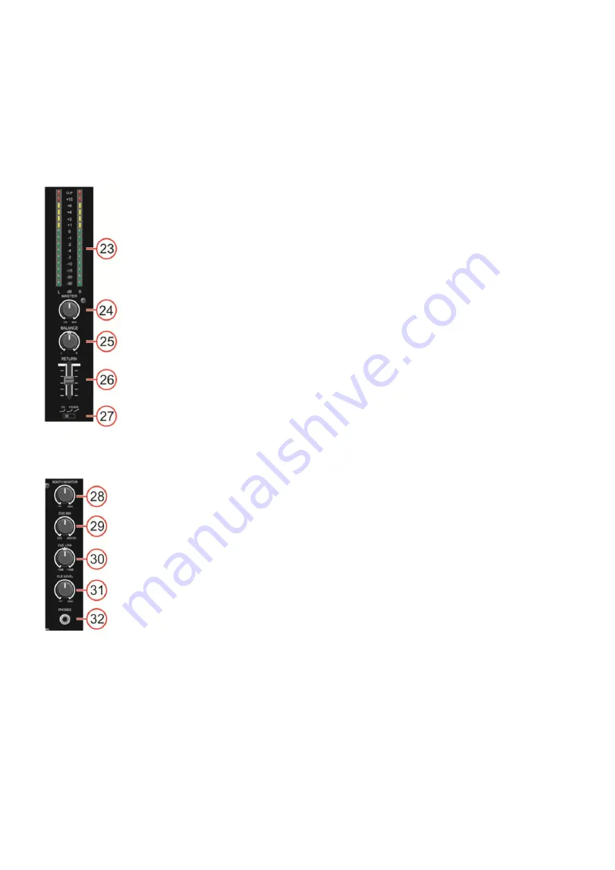
Master section
23. Output L/R signal VU meter
This meter is a multi-step LED; respectively the green LEDs show -30, -20, -15,
-10, -7, -4, -2, -1 and 0dB. The yellow LEDs show +1, +2, +4 and +6dB. The red
LEDs show +10dB and Clip. The accurate level indication allows you to
monitor the output signal level at anytime, and match with other devices.
Lower the
master (24)
control if the Clip LED lights.
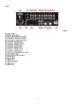
24. Master volume control
Use to adjust the volume level of the
master RCA (46)
or the
master XLR (58)
outputs.
25. Balance
Use
to set the balance between the Left and right master output.
26. Return fader
Use this fader to control the level from the
return (59)
input in the mastermix.
27. Channel fader curve switch
Use this switch to select the curve for all channel faders.
Fig. 10
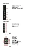
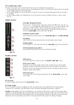
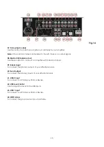
Monitor section
28. Cue level
Is used to adjust the volume level of the
booth monitor (47)
output.
29. Cue mix control
Allows the user to hear mixed audio of the monitor (cue) audio and the
program (master) audio in the headphones. When the knob is rotated to
the left only the cue audio will be heard, when in the right position only the
program audio will be heard.
30. Cue low level
Is used to boost or cut the low frequencies for the
phones (32)
output with
up to 15dB.
Fig. 11
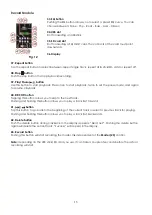
31. Cue level
Is used to adjust volume level of the
phones (32)
output.
32. Phones output
You can connect a pair of headphones with an impedance of 32 - 600 Ohm to the headphones
connector. It is a 6,3mm (
1
/4”) TRS socket, wired as Tip=left, Ring=right and sleeve = ground.
Caution:
Depending on the type of headphones connected to the phones jack, the Core Mix-3 USB is
capable of producing high output levels via the phones output. Therefore, make sure to turn the control
all the way to the left (minimum setting) before connecting the headphones. Be aware of the fact that
listening to loud sound pressure levels over a longer period of time leads to hearing- damage!
Summary of Contents for Core Mix-3 USB
Page 22: ......